FUEL INJECTION CONTROL OPERATION [L3 R.H.D.]


BUE014000000N21

Operation

Injection timing

• There is synchronized fuel injection, which performs fuel injection by the setting of the crankshaft position, and non-synchronized fuel injection which performs fuel injection when the condition for fuel injection is met regardless of the crankshaft position.
Synchronized fuel injection
• The crankshaft rotation is synchronized by each intake and exhaust stroke of the cylinders, and fuel injection is performed by the fuel injection timing and the injection amount corresponding to the input signals of the following sensors.
- CKP sensor
- MAF sensor
- ECT sensor
- IAT sensor
Non-synchronized fuel injection
• The crankshaft rotation is not synchronized and fuel injection is performed by the injection timing and injection amount as triggered by the input signals of the following sensors.
- TP sensor
- MAF sensor
- ECT sensor
- IAT sensor
Relation between synchronized and non-synchronized fuel injection
• If synchronized and non-synchronized fuel injection happen to occur together, fuel is injected by adding the fuel injection timing of both.

Injection time

• The PCM calculates the fuel injection amount according to the engine operation conditions as the fuel injection time and energizes the fuel injectors accordingly.
Fuel injector energization time and operation conditions
• The fuel injectors cause an operation delay with the start of energization from the PCM. The PCM calculates the fuel injection time by adding the non-injection time (ineffective injection time) to the actual injection time (effective injection time), and energizes the fuel injectors for this time.

1
Injection signal
2
Fuel injector current
3
Fuel injector
4
Fuel injection time
5
Ineffective injection time
6
Effective injection time
7
Fuel injector opening valve electrical current
8
Fuel injector valve opening time
9
Open
10
Closed

• The fuel injection time is based on the following formula:

Fuel injection time = effective injection time + ineffective injection time

Ineffective injection time
- The fuel injectors cause an operation delay due to a delay in the rise of operation current due to coil inductance at the start of energization, and by the mass of the needle valve and plunger, and spring resistance. This delay is the ineffective injection time.
- The non-injection time is affected by the change in battery positive voltage. Accordingly, the PCM sets the non-injection time according to the battery voltage.
Effective injection time
- The fuel injector opening valve time which is the actual fuel injection time is called the effective injection amount.

Determination of effective injection time

• The PCM divides the engine operation conditions into control zones according to engine speed and engine load, and determines the effective injection time at each control zone to perform optimum air/fuel ratio control in all engine driving ranges.

1
Start zone
2
Feedback zone
3
High load volume increase zone
4
Excessive speed fuel cut zone
5
Deceleration fuel cut zone
6
Intake air amount
7
Large
8
Engine speed
9
High

Start zone

Purpose
• Improved startability
Control condition
• When engine speed is 500 rpm or less
Determination of fuel injection time
• According to engine coolant temperature (ECT sensor) and engine speed (CKP sensor)

Feedback zone

Purpose
• Improved fuel economy
• Improved exhaust gas purification
Control condition
• During engine operation except high load volume increase and engine start zones
Determination of fuel injection time
• During normal driving, the amounts of various correction types are added to the basic injection time to set to the theoretical air/fuel ratio.

High load volume increase zone

Purpose
• Improved driveability
Control condition
• Either the charging efficiency or the throttle valve opening angle is a given value or more.
Determination of fuel injection time
• Corrections are added to the basic injection amount and the high load coefficient is calculated according to the engine speed, mass intake airflow amount and the throttle valve opening angle.

Excessive speed fuel cut zone

Purpose
• Engine protection
Control condition
• When engine speed is 6,800 rpm or more
• When the engine speed is 5,500 rpm or more and the engine coolant temperature is approx. -10°C {14°F} or more.
• When the vehicle is stopped, engine speed is 4,000 rpm or more, and the engine coolant temperature is approx. 114°C {237°F} or more
Note
• The PCM determines that the driver continues to unintentionally depress the accelerator pedal
Determination of fuel injection time
• The fuel injection time is set to 0 (fuel cut).

Deceleration fuel cut zone

Purpose
• Improved fuel economy
• Prevents overheating of the catalytic converter.
Control condition
• When the engine conditions are as follows (5 s or more has elapsed after shifting the selector lever to either D, S, or L, and 10 s or more has elapsed after engine start):
- Fully-closed throttle valve during deceleration (Charging efficiency at given value or more)
- While driving under load at engine speed of 1,000 rpm or more with charging efficiency at given value or more (MAF sensor normal)
Determination of fuel injection time
• The fuel injection time is set to 0 (fuel cut).

Fuel injection time calculation method table

(*: Fuel injection time base, x: Correction for fuel injection time)


Calculation and determination method for fuel injection time and correction

Control zone

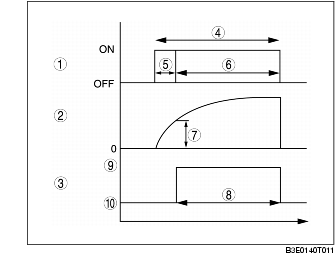
Injection time at start

Set value according to engine coolant temperature (low engine coolant temperature→long injection time)

*


Basic injection time

Basic injection time = charging efficiency x fuel flow coefficient


*

*


Fuel cut

Fuel injection time = 0


*

*

Ineffective injection time

Set time according to injector performance


*

*


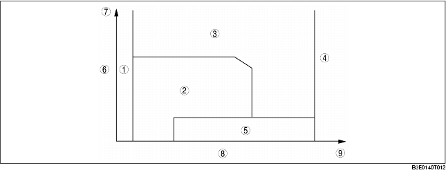
Volume increase correction at engine start
Purpose: Ensures engine speed stability just after engine start
Correction condition
• Specified time according to engine coolant temperature directly after engine start
Correction amount
• Low engine coolant temperature→large correction
• Low intake air temperature→large correction
x
x


Feedback correction
Purpose: Controls air/fuel ratio to theoretical air/fuel ratio
Correction condition
• Engine coolant temperature is at set value or more
Correction amount
• HO2S electromotive force is approx. 0.45 V or more→volume decrease correction
• HO2S electromotive force is approx. 0.45 V or less→volume increase correction
 
x


D-range correction
Purpose: Ensures engine speed stability during D-range shifting
Correction condition
• Throttle valve is fully open and shifting in D range
Correction amount
• Low engine coolant temperature→large correction
 
x


Heavy load volume increase correction
Purpose: Improved engine output, decrease of exhaust gas temperature
Correction condition
• According to engine speed when the throttle valve opening angle is the fixed value or more, otherwise, according to engine speed and charging efficiency
Correction amount
• High engine speed, high charging efficiency→large correction
 
 
x
 
 
Warm-up volume increase correction
Purpose: Ensures combustion stability when engine coolant temperature is low
Correction condition
• While at set engine coolant temperature
Correction amount
• High charging efficiency, low engine coolant temperature→large correction
x
x
x
 
 
A/C and P/S increase correction
 
 
Purpose: Ensures engine speed stability during A/C and P/S operation
Correction condition
• A/C or P/S operating
Correction amount
• Low engine coolant temperature→large correction
 
x
x
 
 
Volume increase correction during acceleration
Purpose: Corrects fuel injection delay during acceleration, to ensure drive stability
Correction condition
• When acceleration amount (change in the amount of charging efficiency) is at the set value or more.
Correction amount
• Low engine coolant temperature→large correction
• Large acceleration amount→large correction
 
x
x
 
 
Deceleration volume increase correction
Purpose: Ensures engine speed stability after fuel cut and fuel cut recovery
Correction condition
• When suddenly entering deceleration fuel cut zone while driving with load, or recovery from fuel cut, the correction value is gradually increased to the set value
Correction amount
• After meeting deceleration fuel cut condition→volume decrease correction
• During fuel cut recovery→volume increase correction


x
Learning correction
Purpose: Corrects deviation in air/fuel ratio from deterioration over time of mechanical devices
Correction condition
• Under any condition except purge control
Correction amount
• Learning value based on average of feedback correction value
 
x
x


Fuel cut

• Includes fuel cut under the following conditions, except fuel cut at excessive engine speed and deceleration fuel cut according to engine operation.

Overspeed fuel cut

Purpose
• To prevent overspeed
Control conditions
• Engine speed 4,000 rpm or more and vehicle speed at given value or more

Fuel cut at shift

Purpose
• To reduce shock during shifting
Control conditions
• During shifting (performs fuel cut on cylinders 1 and 4)

Sensor malfunction fuel cut

Purpose
• To prevent engine damage from abnormal ignition due to a malfunction input of a cylinder identification or the engine speed signal.
Control conditions
• When damage to crankshaft position sensor or camshaft position sensor is detected

Dechoke control

Purpose
• To improve engine startability when spark plugs are flooded.
Control conditions
• When cranking close to fully-open throttle valve