ON-BOARD DIAGNOSTIC SYSTEM OUTLINE [L3]
BUE040200000N01
• The on-board diagnostic system consists of a malfunction detection system that detects abnormalities in input/output signals when the ignition switch is at the ON position, a PID/data monitor function that reads out specified input/output signals and a active command modes function that allows for override operation of output parts (such as solenoid valves).
• The data link connector 2 (DLC-2), which groups together all the connectors used for malfunction diagnosis and detecting/repair into a single location, has been adopted, thereby improving serviceability. Diagnosis is performed by connecting the WDS or equivalent to the DLC-2.
• In addition to DTC read-out, the WDS or equivalent is used to clear DTCs using the display screen of the diagnostic tester, and to access the PID/data monitor and active command modes functions, providing enhanced malfunction diagnosis and improved serviceability.
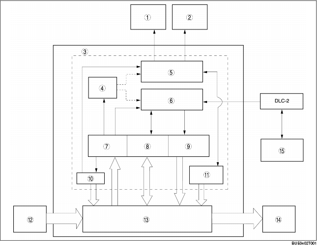
Block Diagram
|
1
|
ABS warning light
|
|
2
|
Brake system warning light
|
|
3
|
On-board diagnostic function
|
|
4
|
Memory function
|
|
5
|
Malfunction display function
|
|
6
|
Serial communication
|
|
7
|
Malfunction detection function
|
|
8
|
PID/DATA monitor function
|
|
9
|
Active command modes function
|
|
10
|
Fail-safe function
|
|
11
|
HU inspection function
|
|
12
|
Input device
|
|
13
|
Normal control area
|
|
14
|
Output device
|
|
15
|
WDS or equivalent
|