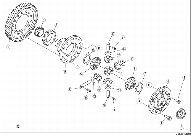
DIFFERENTIAL OUTLINE [G15M-R, G25MX-R]
BUE051500000N22
|
1
|
Bolt
|
|
2
|
Ring gear
|
|
3
|
Screw
|
|
4
|
Differential cover
|
|
5
|
Bearing
|
|
6
|
Speedometer driver gear
|
|
7
|
Thrust washer
|
|
8
|
Side gear
|
|
9
|
Roll pin
|
|
10
|
Pinion shaft
|
|
11
|
Pinion carrier
|
|
12
|
Pinion gear
|
|
13
|
Thrust washer
|
|
14
|
Side gear
|
|
15
|
Thrust washer
|
|
16
|
Gear case
|
|
17
|
The figure shows G15M-R
|
• The ends of the differential are supported on tapered roller bearings. The cups for these bearings are seated in the transaxle case and the clutch housing. Bearing preload is set using a selective bearing shim that is installed under the bearing cup in the transaxle case.
• The differential includes the side gears and the shaft mounted pinion gears. Direct contact between the gears and the gear case is prevented by the side gear thrust washers installed under the gears. The pinion shaft is held in position by a roll pin that extends through the end of the pinion shaft and the gear case.
• The speedometer drive gear is also mounted on the gear case. It is located between the tapered roller bearing and the gear case. A tab on the speedometer drive gear and a matching slot in the gear case prevent the speedometer drive gear from spinning on the gear case.
