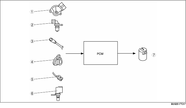
3-2 TIMING CONTROL STRUCTURE [GF4AX-EL]


BUE051718880N08

Features

• Based on input signals from switches and sensors, the PCM determines the optimal shift timing according to shift conditions and outputs corresponding on/off signals to the 3-2 timing solenoid, thereby reducing shift shock.

Structure

Block Diagram

1
TR switch
2
Input/turbine speed sensor
3
O/D OFF switch
4
TP sensor
5
ABS wheel-speed sensor
6
TFT sensor
7
3-2 timing solenoid