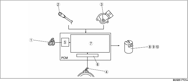
SHIFT CONTROL STRUCTURE [GF4AX-EL]


BUE051721101N15

Features

• The PCM selects and determines automatic shift patterns based on determination of range and driving modes. Based on the selected pattern, and according to reverse and forward drum speeds (vehicle speed) and throttle opening angle, a gear position is determined and the PCM sends a signal to the solenoid valves.

Structure

System Diagram

1
TP sensor
2
O/D OFF switch
3
TR switch
4
Input/turbine speed sensor
5
Throttle opening angle
6
Vehicle speed
7
Shift diagram
8
Shift solenoid A
9
Shift solenoid B
10
Shift solenoid C