SHIFT-LOCK SYSTEM STRUCTURE
BUE051830000N02
Structure
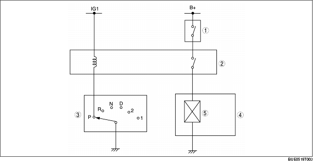
• The shift-lock system consists of the shift-lock relay, brake switch, TR switch, shift-lock solenoid, and selector lever component.
|
1
|
Brake switch
|
|
2
|
Shift-lock relay
|
|
3
|
TR switch
|
|
4
|
Selector lever component
|
|
5
|
Shift-lock solenoid
|
Operation
Shift-lock release condition
-
• The shift-lock is released when the selector lever at P position (TR switch at P position), ignition switch is at the ON position, and the brake pedal is depressed.
Shift-lock (when the shift-lock conditions are not satisfied)
-
• When the shift-lock conditions are not satisfied, electrical current does not flow to the shift-lock solenoid from the shift-lock relay. The lock lever therefore mechanically restricts the movement of the selector lever, preventing shifting out of Park.

|
1
|
Selector lever
|
|
2
|
Lock lever
|
|
3
|
Shift-lock solenoid
|
Shift-lock release (when the shift-lock conditions are satisfied)
-
• When the shift-lock conditions are satisfied, electrical current flows to the shift-lock solenoid from the shift-lock relay. The slider therefore moves toward the shift-lock solenoid and the lock lever moves to a position in which it does not restrict movement of the selector lever, allowing shifting out of Park.

|
1
|
Selector lever
|
|
2
|
Lock lever
|
|
3
|
Slider
|
|
4
|
Shift-lock solenoid
|
Shift-lock release (when inserting a screwdriver into the shift-lock release hole.)
-
• By pushing the shift-lock release lever down, the lock lever is pushed up to a position where it does not restrict movement of the selector lever.

|
1
|
Selector lever
|
|
2
|
Lock lever
|
|
3
|
Shift-lock release lever
|