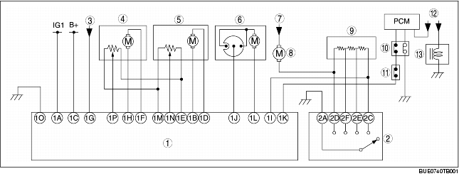
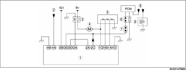
CONTROL SYSTEM WIRING DIAGRAM


BUE074000000N02

L.H.D.

1
Climate control unit
2
TNS relay
3
Blower relay
4
Blower motor
5
Resistor
6
Refrigerant pressure switch
7
A/C cycling switch
8
A/C relay
9
Magnetic clutch

R.H.D.

1
Climate control unit
2
Fan switch
3
TNS relay
4
Airflow mode actuator
5
Air mix actuator
6
Air intake actuator
7
Blower relay
8
Blower motor
9
Resistor
10
Refrigerant pressure switch
11
A/C cycling switch
12
A/C relay
13
Magnetic clutch