RESISTOR CONSTRUCTION
BUE074061015N01
• The four-speed operation of the blower motor.
• The resistor located on the passenger side on the cooling unit behind the glove compartment.
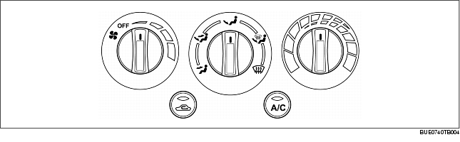
CLIMATE CONTROL UNIT CONSTRUCTION/OPERATION
L.H.D.
-
• The climate control unit has five system controls:
-
- The mode switch combines a vacuum selector valve with two electrical switches to supply battery positive voltage (B+) to the magnetic clutch circuit and the blower motor control circuit.
-
- The temperature selection is accomplished through cable controlled positioning of the air mix door located in the heater unit.
-
- The fan control switch combines three system controls, a vacuum selector valve with two electrical switches to control the blower motor speed, fresh air circulation, and A/C compressor operation.
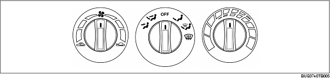
R.H.D.
-
• The climate control unit has five system controls:
-
- The mode switch operates the airflow mode actuator to provide defrost, vent, and floor air distribution. The magnetic clutch is engaged in the defrost mode.
-
- Temperature selection is accomplished with a potentiometer connected to the air mix actuator. Movement of the control knob from cool to warm causes a corresponding movement on the air mix door and determines the temperature that the system will maintain.
-
- The fan control switch controls the blower motor speed by adding or bypassing resistors in the resistor.
-
- An A/C compressor control push-button switch with an illuminated ON light.
-
- A fresh air/recirculate push-button switch with an illuminated ON light to indicate recirculationing air.