|
DTC
|
System malfunction location
|
|
WDS or equivalent display
|
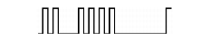
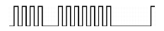
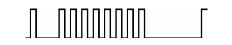
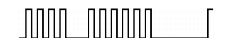
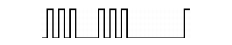
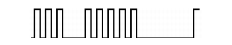
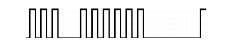
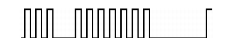
Air bag system warning light
|
|
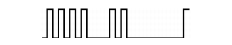
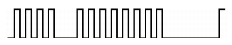
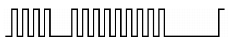
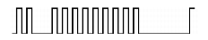
Flashing pattern
|
Priority ranking
|
|
B1231
|
19
|

|
3
|
SAS control module activation (deployment) control frequency error
|
|
B1342
|
24
|
|
2
|
SAS control module internal malfunction
|
|
B1869
|
-
|
Warning sound
|
30
|
Air bag system warning light operation malfunction
|
|
B1870
|
31
|
Air bag system warning light circuit short to power supply
|
|
B1877
|
46
|

|
26
|
Driver-side pre-tensioner front buckle circuit resistance high
|
|
B1878
|
17
|

|
30
|
Driver-side pre-tensioner front buckle circuit short to power supply
|
|
B1879
|
Driver-side pre-tensioner front buckle circuit short to body ground
|
|
B1881
|
47
|
|
26
|
Passenger-side pre-tensioner front buckle circuit resistance high
|
|
B1882
|
18
|
|
31
|
Passenger-side pre-tensioner front buckle circuit short to power supply
|
|
B1883
|
Passenger side pre-tensioner front buckle circuit short to body ground
|
|
B1885
|
46
|
|
26
|
Driver-side pre-tensioner front buckle resistance low
|
|
B1886
|
47
|

|
27
|
Passenger-side pre-tensioner front buckle circuit resistance low
|
|
B1887
|
15
|

|
6
|
Driver-side air bag module circuit short to body ground
|
|
B1888
|
16
|

|
7
|
Passenger side air bag module circuit short to body ground
|
|
B1891
|
-
|
Warning sound
|
29
|
Air bag warning sound circuit short to power supply
|
|
B1892
|
28
|
Air bag warning sound short to body ground
|
|
B1916
|
15
|

|
8
|
Driver-side air bag module circuit short to power supply
|
|
B1921
|
21
|

|
4
|
SAS control module ground bracket resistance high
|
|
B1925
|
16
|

|
9
|
Passenger-side air bag module circuit short to power supply
|
|
B1932
|
32
|

|
10
|
Driver-side air bag module circuit resistance high
|
|
B1933
|
33
|
|
11
|
Passenger-side air bag module circuit resistance high
|
|
B1934
|
34
|

|
12
|
Driver-side air bag module circuit resistance low
|
|
B1935
|
35
|
|
13
|
Passenger-side air bag module circuit resistance low
|
|
B1992
|
36
|
|
21
|
Driver-side side air bag module circuit short to power supply
|
|
B1993
|
20
|
Driver-side side air bag module circuit short to body ground
|
|
B1994
|
22
|
Driver-side side air bag module circuit resistance high
|
|
B1995
|
23
|
Driver-side side air bag module circuit resistance low
|
|
B1996
|
37
|
|
25
|
Passenger-side side air bag module circuit short to power supply
|
|
B1997
|
24
|
Passenger-side side air bag module circuit short to body ground
|
|
B1998
|
26
|
Passenger-side side air bag module circuit resistance high
|
|
B1999
|
27
|
Passenger-side side air bag module circuit resistance low
|
|
B2440
|
43
|

|
17
|
Passenger-side side air bag sensor installation malfunction
|
|
B2441
|
42
|
|
16
|
Driver-side side air bag sensor installation malfunction
|
|
B2444
|
48
|
|
14
|
Driver-side side air bag sensor (internal circuit abnormal)
|
|
B2445
|
49
|
|
15
|
Passenger-side side air bag sensor (internal circuit abnormal)
|
|
C1414
|
29
|
|
5
|
Vehicle identification code error
|
|
U2017
|
44
|

|
18
|
Driver-side side air bag sensor (communication error)
|
|
U2018
|
45
|

|
19
|
Passenger-side side air bag sensor (communication error)
|