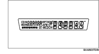
ON-BOARD DIAGNOSTIC SYSTEM OPERATION [AUDIO SYSTEM]


BUE092066900N10

Self-diagnostic Function

Malfunction detection function

• The malfunction detection section detects malfunctions occurring in the system.

Memory function

• The memory function detects a malfunction, changes it to a DTC, and stores it in the memory. The memory can store a maximum of three DTCs. If another malfunction is detected when three DTCs are already stored, the memory function clears the oldest DTC and stores the new one.
• Once a DTC is stored, it can only be cleared by the designated procedure; not by turning the ignition switch to the LOCK position or disconnecting the negative battery cable. The procedure is mentioned in the Workshop Manual.

Display function

• When the self-diagnostic function is activated, the LCD displays the DTC stored in the memory.
• The DTC consists of the following codes and numbers:
- Part number (indicates malfunctioning part)
- Error code (indicates malfunction description)
- Manufacture code (indicates manufacturer)
• Refer to the Workshop Manual for the display method.

Supplier code

Supplier name

1
FMS Audio
2
Panasonic
3
Clarion

Parts number

Parts name

00
Cassette deck (lower module)
03
CD player (upper module)
05
CD changer (external type)
06
CD changer (upper module)
07
MD player (lower module)
09
Base unit

Error code

Malfunction description

01
Internal mechanism error
02
Servo mechanism error
03
Mechanism stuck
07
Disc reading error
10
BUS line (communication line) error
20
Insufficient power supply
22
Tuner error

Screen display

Malfunction location

DTC

Output signal

09:Er22
-
Base unit (peripheral circuit)
09:Er20
-
Power supply circuit of base unit
00:Er10
-
Cassette deck-base unit communication line
03:Er10
-
CD player-base unit communication line
05:Er10
-
CD changer (upper module)-base unit communication line
06:Er10
-
CD changer (external type)-base unit communication line
07:Er10
-
MD player-base unit communication line
03:Er01
-
CD player
03:Er02
CHECK*1 CD*2
CD player
03:Er07
CHECK*1 CD*2
CD player
00:Er01
-
Cassette deck
00:Er03
-
Cassette deck
00:Er04
CHECK*1 TAPE*2
Cassette deck
05:Er01
-
CD changer (external type)
05:Er07
CHECK*1 CD*2
CD changer (external type)
06:Er01
-
CD changer (upper module)
06:Er02
CHECK*1 CD*2
CD changer (upper module)
06:Er07
CHECK*1 CD*2
CD changer (upper module)
07:Er01
-
MD player
07:Er02
CHECK*1 MD*2
MD player
07:Er07
CHECK*1 MD*2
MD player
no Er
-
No stored DTCs

*1,*2 :
When an error occurs, the error messages are displayed three times in the order of *1 and *2, respectively.

Diagnostic Assist Function

• The diagnostic assist function displays the operating condition of the following functions (components) and forces them to operate in order to examine whether they are malfunctioning or not.
• For the start procedure of each mode, refer to the Workshop Manual.

LCD

• The diagnostic assist function illuminates all characters in the LCD to check for truncated or faint characters.

Switch

• The diagnostic assist function sounds the buzzer when the switches are pressed to check the switches.

Speaker

• The diagnostic assist function outputs sound to the speakers in the following order to determine condition of the speakers and wiring harness between the base unit and each speaker.
- If the vehicle equipped with a woofer, the woofer outputs sound at the same time as the rear speakers.
1. Left door speaker and tweeter
2. Right door speaker and tweeter
3. Left rear speaker
4. Right rear speaker

Radio

• The diagnostic assist function displays the radio reception condition with the volume indicator bar (nine graduations) to determine condition of the antenna, antenna feeders, and base unit (tuner).

Power antenna

• The diagnostic assist function displays the output state of the power antenna operating signal to determine condition of the power antenna, base unit, and wiring harness between the base unit and power antenna.