Diagnostic procedure
|
STEP
|
INSPECTION
|
ACTION
|
|
|---|---|---|---|
|
1
|
VERIFY FREEZE FRAME DATA HAS BEEN RECORDED
• Has FREEZE FRAME DATA been recorded?
|
Yes
|
Go to next step.
|
|
No
|
Record FREEZE FRAME DATA on repair order, then go to next step.
|
||
|
2
|
VERIFY RELATED SERVICE INFORMATION AVAILABILITY
• Check for related Service Information availability.
• Is any related Service Information available?
|
Yes
|
Perform repair or diagnosis according to available Service Information.
• If vehicle is not repaired, go to next step.
|
|
No
|
Go to next step.
|
||
|
3
|
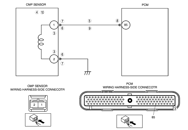
VERIFY CMP SENSOR VOLTAGE
• Disconnect CMP sensor connector.
• Connect voltmeter between CMP sensor connector terminals 1 and 2 (sensor-side).
• Check the voltage in AC range while cranking the engine.
• Is there any voltage reading?
|
Yes
|
Go to step 5.
|
|
No
|
Go to next step.
|
||
|
4
|
INSPECT CMP SENSOR
• Turn ignition key to OFF.
• Perform CMP sensor inspection.
• Is CMP sensor normal?
|
Yes
|
Check camshaft pulley for damage. Replace pulley and go to Step 11.
|
|
No
|
Replace CMP sensor, then go to Step 11.
|
||
|
5
|
CHECK CMP CIRCUIT FOR SHORT TO GROUND
• Disconnect CMP sensor connector.
• Check continuity between following terminal and body ground:
• Is there any continuity?
|
Yes
|
Repair or replace suspected harness, then go to Step 11.
|
|
No
|
Go to next step.
|
||
|
6
|
INSPECT CMP CIRCUITS FOR SHORTS
• Check continuity between CMP sensor connector terminals A and B (harness-side).
• Is there any continuity?
|
Yes
|
Repair or replace suspected harness, then go to Step 11.
|
|
No
|
Go to step 9.
|
||
|
7
|
INSPECT CMP SENSOR CONNECTOR FOR POOR CONNECTION
• Verify that the CMP sensor connector is connected securely.
• Is connector normal?
|
Yes
|
Go to next step.
|
|
No
|
Reconnect the connector, then go to Step 11.
|
||
|
8
|
INSPECT PCM CONNECTOR FOR POOR CONNECTION
• Turn ignition key to OFF.
• Disconnect PCM connector.
• Check for poor connection (damaged, pulled-out terminals, corrosion, etc.).
• Is there any malfunction?
|
Yes
|
Repair terminal, then go to Step 11.
|
|
No
|
Go to next step.
|
||
|
9
|
INSPECT CMP CIRCUIT FOR OPEN CIRCUIT
• Disconnect CMP sensor connector.
• Disconnect PCM connector.
• Check continuity between following circuits:
• Is there any continuity?
|
Yes
|
Go to next step.
|
|
No
|
Repair or replace suspected harness, then go to Step 11.
|
||
|
10
|
INSPECT CMP SENSOR
• Turn ignition key to OFF.
• Perform CMP sensor inspection.
• Is CMP sensor normal?
|
Yes
|
Check for poor connection (damaged, pulled-out terminals, corrosion, etc.) or bent terminal of CMP sensor connector.
• Repair if necessary, then go to next step.
|
|
No
|
Replace CMP sensor and then go to next step.
|
||
|
11
|
VERIFY TROUBLESHOOTING OF DTC P0340 COMPLETED
• Make sure to reconnect all disconnected connectors.
• Turn ignition key ON (engine OFF).
• Clear DTC from memory using WDS or equivalent.
• Start engine.
• Access MAF PID using WDS or equivalent.
• Is pending code of same DTC present?
|
Yes
|
Replace PCM, then go to next step.
|
|
No
|
Go to next step.
|
||
|
12
|
VERIFY AFTER REPAIR PROCEDURE
• Perform "After Repair Procedure".
• Is there any DTC present?
|
Yes
|
Go to applicable DTC inspection.
(See DTC TABLE [YF (2.0L Zetec)].)
|
|
No
|
Troubleshooting completed.
|
||