Diagnostic procedure
|
STEP
|
INSPECTION
|
ACTION
|
|
|---|---|---|---|
|
1
|
VERIFY FREEZE FRAME DATA HAS BEEN RECORDED
• Has FREEZE FRAME PID DATA been recorded?
|
Yes
|
Go to next step.
|
|
No
|
Record FREEZE FRAME PID DATA on repair order, then go to next step.
|
||
|
2
|
VERIFY RELATED SERVICE INFORMATION AVAILABILITY
• Check for related Service Information availability.
• Is any related Service Information available?
|
Yes
|
Perform repair or diagnosis according to available Service Information.
• If vehicle is not repaired, go to next step.
|
|
No
|
Go to next step.
|
||
|
3
|
VERIFY CURRENT INPUT SIGNAL STATUS-IS CONCERN INTERMITTENT OR CONSTANT
• Connect WDS or equivalent to DLC-2.
• Start engine.
• Access VSS PID using WDS or equivalent.
• Are PID readings appropriate?
|
Yes
|
Go to intermittent concern troubleshooting procedure.
|
|
No
|
Go to next step.
|
||
|
4
|
INSPECT POOR CONNECTION OF VSS CONNECTOR
• Verify that the VSS connector is connected securely.
• Is connector normal?
|
Yes
|
Go to next step.
|
|
No
|
Reconnect the connector, then go to Step 11.
|
||
|
5
|
INSPECT VSS
• Perform the VSS inspection.
• Is the VSS normal?
|
Yes
|
Go to next step.
|
|
No
|
Replace the VSS, then go to Step 11.
|
||
|
6
|
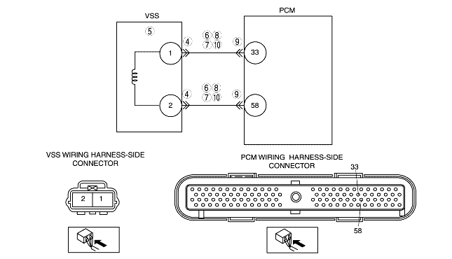
INSPECT VSS CIRCUIT FOR SHORT TO POWER
• Turn the ignition switch off.
• Disconnect the VSS connector.
• Turn the ignition switch to the ON position (engine off).
• Measure voltage following terminals:
• Is any voltage reading?
|
Yes
|
Repair or replace suspected wiring harness, then go to Step 11.
|
|
No
|
Go to next step.
|
||
|
7
|
INSPECT VSS CIRCUIT FOR SHORT TO GROUND
• Inspect continuity between following terminal and body ground:
• Is there continuity?
|
Yes
|
Repair or replace suspected wiring harness, then go to Step 11.
|
|
No
|
Go to next step.
|
||
|
8
|
INSPECT VSS CIRCUITS FOR SHORTS
• Inspect continuity between the VSS connector terminals (wiring harness-side) 1 and 2.
• Is there continuity?
|
Yes
|
Repair or replace suspected wiring harness, then go to Step 11.
|
|
No
|
Go to next step.
|
||
|
9
|
INSPECT POOR CONNECTION OF PCM CONNECTOR
• Disconnect the PCM connector.
• Inspect for poor connection (such as damaged, pulled-out pins, and corrosion).
• Is there any malfunction?
|
Yes
|
Repair terminal, then go to Step 11.
|
|
No
|
Go to next step.
|
||
|
10
|
INSPECT VSS CIRCUIT FOR OPEN CIRCUIT
• Inspect continuity between following terminals:
• Is there continuity?
|
Yes
|
Inspect VSS pulse wheel for damage. Replace the VSS pulse wheel and go to next step.
|
|
No
|
Repair or replace suspected wiring harness, then go to next step.
|
||
|
11
|
VERIFY TROUBLESHOOTING OF DTC P0500 COMPLETED
• Make sure to reconnect all disconnected connectors.
• Turn the ignition switch to the ON position (engine off).
• Clear the DTC from the PCM memory using WDS or equivalent.
• Warm up engine.
• Access RPM and LOAD PID using WDS or equivalent.
• Drive the vehicle under the following conditions.
• Is PENDING CODE same as DTC present?
|
Yes
|
Replace the PCM, then go to the next step.
|
|
No
|
Go to next step.
|
||
|
12
|
VERIFY AFTER REPAIR PROCEDURE
• Perform "AFTER REPAIR PROCEDURE".
• Are any DTCs present?
|
Yes
|
Go to applicable DTC troubleshooting.
(See DTC TABLE [YF (2.0L Zetec)].)
|
|
No
|
Troubleshooting completed.
|
||