1. Disconnect the negative battery cable.
2. Disconnect the high tension leads from the spark plugs. (See SPARK PLUG REMOVAL/INSTALLATION [L3].)
3. Remove the splash shield (RH).
4. Remove the front wheel and tire (RH).
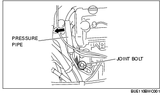
5. Remove the pressure pipe bracket of the P/S oil pump.
6. Loosen the pressure pipe joint bolt of the P/S oil pump, move the pressure pipe to the right side of the vehicle, position the cylinder head cover out of the way, and then temporarily tighten the bolt.
7. Remove the cylinder head cover.
8. Remove the drive belt. (See DRIVE BELT REPLACEMENT [L3].)
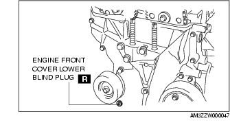
9. Remove the engine front cover lower blind plug.
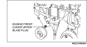
10. Remove the engine front cover upper blind plug.
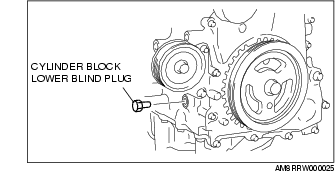
11. Remove the cylinder block lower blind plug.
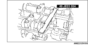
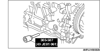
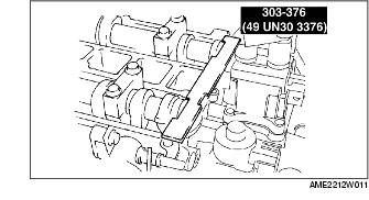
12. Install the SST as shown.
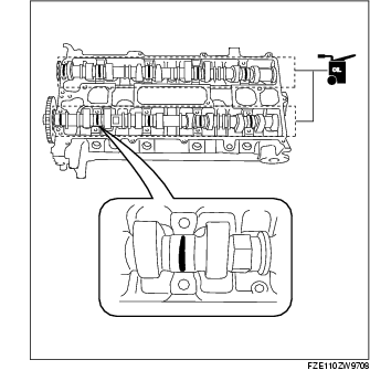
13. Turn the crankshaft clockwise the crankshaft is in No.1 cylinder TDC position.
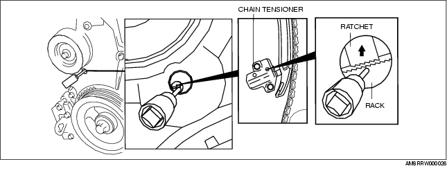
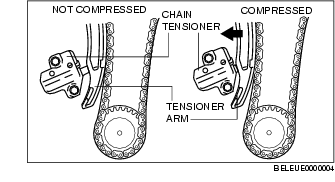
14. Loosen the timing chain using the following procedure.


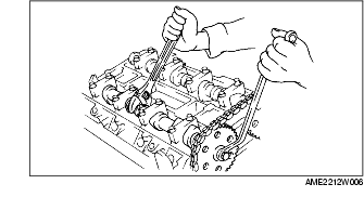
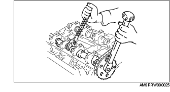
15. Hold the exhaust camshaft using a suitable wrench on the cast hexagon as shown.
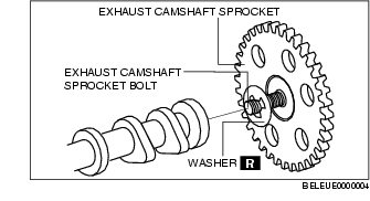
16. Remove the exhaust camshaft sprocket bolt, exhaust camshaft sprocket, and washer as a single unit.
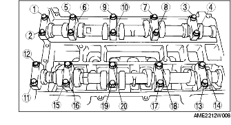
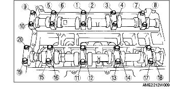
17. Loosen the camshaft cap bolts in two or three steps in the order shown.
18. Remove the camshaft.
19. Remove the tappet.
20. Select proper adjustment shim.
New adjustment shim21. Apply the gear oil (SAE No. 90 or equivalent) to each journal of the cylinder head as shown in the figure.
22. Install the camshaft with No.1 cylinder aligned with the TDC position.
23. Apply the gera oil (SAE No. 90 or equivalent) to each journal of the camshaft as shown in the figure.
24. Tighten the camshaft cap bolt with the following two steps.

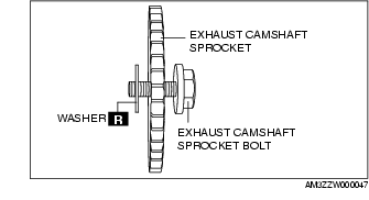
25. Install the exhaust camshaft sprocket bolt, exhaust camshaft sprocket, and a new washer as a single unit.
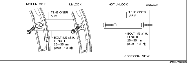
26. Install the SST to the camshaft as shown.
European countries
Except European countries
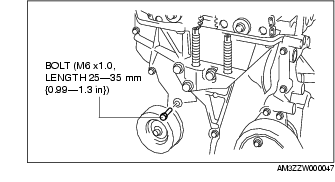
27. Remove the M6 x 1.0 bolt from the engine front cover to apply tension to the timing chain.
28. Turn the crankshaft clockwise until the crankshaft is in the No.1 cylinder TDC position (until the balance weight is attached to the SST).
29. Hold the exhaust camshaft using a suitable wrench on the cast hexagon as shown.
30. Tighten the exhaust camshaft sprocket bolt.
31. Remove the SST from the camshaft.
32. Remove the SST from the block lower blind plug.
33. Rotate the crankshaft clockwise two turns until the TDC position.
34. Apply silicone sealant to the engine front cover upper blind plug.
35. Install the engine front cover upper blind plug.
36. Install the cylinder block lower blind plug.
37. Install the engine front cover lower new blind plug.
38. Install the drive belt. (See DRIVE BELT REPLACEMENT [L3].)
39. Install the splash shield (RH).
40. Install the front wheel and tire(RH).
41. Install the cylinder head cover. (See Cylinder Head Cover Installation Note.)
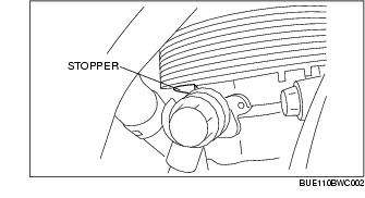
42. Loosen the pressure pipe joint bolt, move the pressure pipe joint until it contacts the stopper to return the pipe to its original position and then tighten the bolt.
43. Install the pressure pipe bracket of the P/S oil pump.
44. Disconnect the high-tension cord.(See SPARK PLUG REMOVAL/INSTALLATION [L3].)
1. Disconnect the negative battery cable.
2. Remove the ignition coil.
3. Remove the splash shield (RH).
4. Remove the front wheel and tire(RH).
5. Remove the cylinder head cover.
6. Remove the drive belt. (See DRIVE BELT REPLACEMENT [L3].)
7. Remove the engine front cover lower blind plug.
8. Remove the engine front cover upper blind plug.
9. Remove the cylinder block lower blind plug.
10. Install the SST as shown.
11. Turn the crankshaft clockwise the crankshaft is in No.1 cylinder TDC position.
12. Loosen the timing chain using the following procedure.


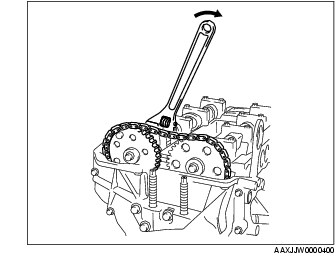

13. Hold the exhaust camshaft using a suitable wrench on the cast hexagon as shown.
14. Remove the exhaust camshaft sprocket bolt, exhaust camshaft sprocket, and washer as a single unit.
15. Loosen the camshaft cap bolts in two or three steps in the order shown.
16. Remove the camshaft.
17. Remove the tappet.
18. Select proper adjustment shim.
New adjustment shim19. Apply the gear oil (SAE No. 90 or equivalent) to each journal of the cylinder head as shown in the figure.
20. Install the camshaft with No.1 cylinder aligned with the TDC position.
21. Apply the gera oil (SAE No. 90 or equivalent) to each journal of the camshaft as shown in the figure.
22. Tighten the camshaft cap bolt with the following two steps.
23. Install the exhaust camshaft sprocket bolt, exhaust camshaft sprocket, and a new washer as a single unit.
24. Install the SST to the camshaft as shown.
European countries
Except European countries
25. Remove the M6 x 1.0 bolt from the engine front cover to apply tension to the timing chain.
26. Turn the crankshaft clockwise until the crankshaft is in the No.1 cylinder TDC position (until the balance weight is attached to the SST).
27. Hold the exhaust camshaft using a suitable wrench on the cast hexagon as shown.
28. Tighten the exhaust camshaft sprocket bolt.
29. Remove the SST from the camshaft.
30. Remove the SST from the block lower blind plug.
31. Rotate the crankshaft clockwise two turns until the TDC position.
32. Apply silicone sealant to the engine front cover upper blind plug.
33. Install the engine front cover upper blind plug.
34. Install the cylinder block lower blind plug.
35. Install the engine front cover lower new blind plug.
36. Install the drive belt. (See DRIVE BELT REPLACEMENT [L3].)
37. Install the splash shield (RH).
38. Install the front wheel and tire(RH).
39. Install the cylinder head cover. (See Cylinder Head Cover Installation Note.)
40. Install the ignition coil.