THROTTLE POSITION (TP) SENSOR INSPECTION [L3 R.H.D.]
id0140a7802700
-
Note
-
• Before performing the following inspection, make sure to follow the procedure as indicated in the troubleshooting flowchart. (See Troubleshooting Procedure.)
Resistance Inspection
1. Verify the following items:
-
• Throttle valve closed status
-
• Accelerator cable play
-
- If the PID value is not within the specification, even though the items above are normal, perform the following resistance variance inspection.
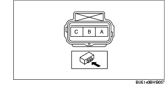
2. Disconnect the TP sensor connector.
3. Using a tester, verify that the resistance between TP sensor terminals A and B changes moderately corresponding to the throttle valve openings.
-
• If it can be verified, go to the next step.
-
• If it cannot be verified, replace the TP sensor.
4. Using a tester, measure the resistance between TP sensor A-C terminals.
-
• If it is within the specification, perform the Circuit Open/Short Inspection, then repair or replace the malfunctioning part.
-
• If it is not within the specification, replace the TP sensor.
-
Standard
-
3.0-5.0 kilohms