1. Lift up the vehicle.
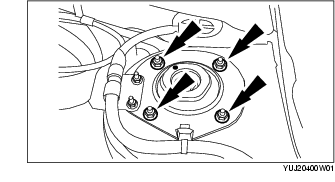
2. Remove the front shock absorber upper mounting bracket nuts.
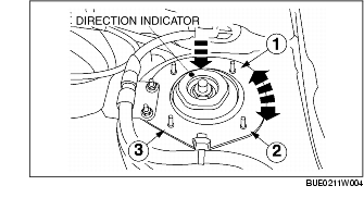
3. Push the front shock absorber upper mounting bracket downward and turn it to the desired position to set camber and caster. Both camber and caster for front suspension are adjustable within a maximum angle of 22' minutes.
|
Direction indicator
|
Difference from standard position
|
|
|---|---|---|
|
Camber angle
|
Caster angle
|
|
|
1
|
0°
|
-0°22' 12''
|
|
2
|
-0°21' 36''
|
-0°22' 12''
|
|
3
|
-0°21' 36''
|
0°
|
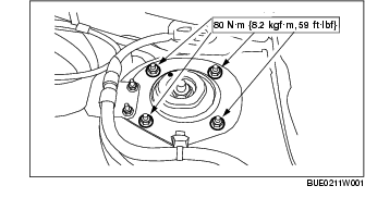
4. Tighten the front shock absorber upper mounting bracket nuts.
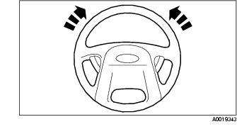
1. Start the engine and center the steering wheel.
2. Turn the engine off and lock the steering wheel in position.
3. Inspect the toe settings. Follow the specifications.
4. Remove the clamps.
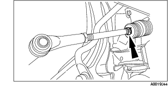
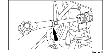
5. Loosen the nuts.
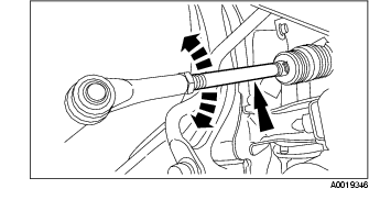
6. Rotate the nuts and the front wheel spindle tie rods.
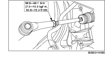
7. Tighten the nuts.
8. Install the clamp(s).
9. Inspect the toe settings again. Follow the specifications.