1. Remove the drive shaft. (See FRONT DRIVE SHAFT REMOVAL/INSTALLATION.)
2. Secure the drive shaft in a vice using protective jaw covers.
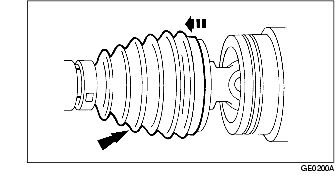
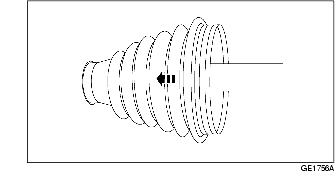
3. Remove the boot band.
4. Slide and remove the boot.
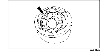
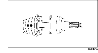
5. Disconnect the tripod joint from the outer ring.
6. If reinstalling the tripod joint, mark the tripod joint and the drive shaft for correct installation.
7. Remove the snap ring.
8. Remove the tripod joint.
9. Remove the boot from the drive shaft.
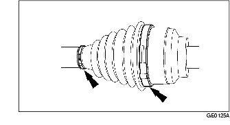
10. Remove the two boot bands (wheel side).
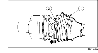
11. Slide the boot back out of the way to expose the joint (wheel side).
12. Remove and dispose the retainer clip.
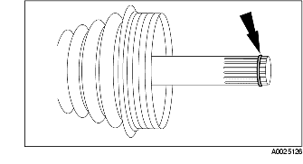
13. Slide and remove the boot (wheel side) from the drive shaft.
1. Lubricate the joint (wheel side) with the BALL JOINT ADDITIVE.
2. Install the boot.
3. Install a new retainer clip.
4. Remove any excess grease on the mating surfaces and slide the boot forward onto the joint.
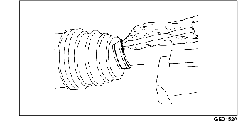
5. Remove any excess air trapped in the boot using a cloth covered screwdriver after installing the boot correctly.
6. Assemble a new boot band.

7. Fill the boot with the repair kit grease.
8. Position the boot (differential side).
9. Install the tripod joint to the drive shaft.
10. Install the snap ring.
11. Lubricate the three tripod joint needle bearings.
12. Lubricate inside the tripod joint with the BALL JOINT ADDITIVE.
13. Position the outer ring onto the tripod.
14. Position the boot (differential side).
15. Remove any excess air trapped in the boot using a cloth covered screwdriver after installing the boot correctly.
16. Follow the same procedures to install the two new boot bands on the opposite side.
17. Install the drive shaft. (See FRONT DRIVE SHAFT REMOVAL/INSTALLATION.)