RBC UNIT DISASSEMBLY/ASSEMBLY
id031800800200
|
1
|
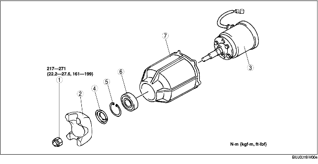
Locknut
|
|
2
|
Yoke
|
|
3
|
RBC unit
|
|
4
|
Oil seal
|
|
5
|
Retaining ring
|
|
6
|
Bearing
|
|
7
|
Coupling case
|
-
Caution
-
• When removing/installing the yoke, make sure the spline connection does not move from its original phase because the rotary blade coupling is balanced.
-
• If the replacement of the rotary blade coupling is necessary, replace the rotary blade coupling component as a single unit to prevent improper balance.
Disassembly
1. Remove the rotary blade coupling. (See RBC UNIT REMOVAL/INSTALLATION.)
2. Install the SSTs to the engine stand.
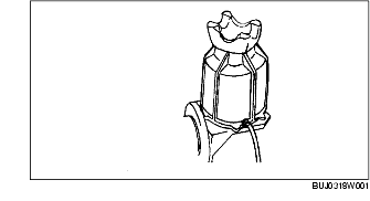
3. Install the RBC unit on the SST as shown in the figure.
-
Warning
-
• The engine stand is equipped with a self-lock mechanism. However, if the RBC unit is tilted, the self-lock mechanism could become inoperative. This could cause the RBC unit to rotate accidentally, resulting in injury. Therefore, make sure that the RBC unit is not tilted when it is on the engine stand. When turning RBC unit, grasp the rotation handle firmly.
4. Hold the yoke using the SST and remove the locknut.
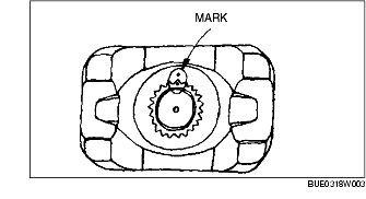
5. Place alignment marks on the yoke and the shaft using a punch.
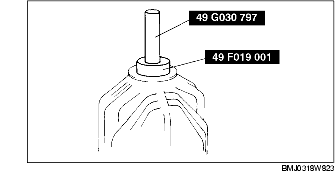
6. Remove the yoke using the SST.
7. Remove the RBC unit from the SST.
8. Remove the RBC unit from the coupling case.
9. Remove the oil seal.
10. Remove the retaining ring.
11. Remove the bearing from the coupling case using the SSTs.
Assembly
-
Warning
-
• The engine stand is equipped with a self-lock mechanism. However, if the RBC unit is tilted, the self-lock mechanism could become inoperative. This could cause the RBC unit to rotate accidentally, resulting in injury. Therefore, make sure that the RBC unit is not tilted when it is on the engine stand. When turning RBC unit, grasp the rotation handle firmly.
1. Install the bearing to the coupling case using the SSTs.
2. Install the retaining ring.
3. Assemble the RBC unit to the coupling case.
4. Apply the genuine long-life hypoid gear oil to a new oil seal lip.
5. Assemble the oil seal to the coupling case using the SST.
6. Assemble the yoke.
-
Caution
-
• Align the alignment marks on the shaft and the yoke placed when disassembly.
7. Hold the yoke using the SST and tighten the locknut.
-
Tightening torque
-
217-271 N·m {22.2-27.6 kgf·m, 161-199 ft·lbf}