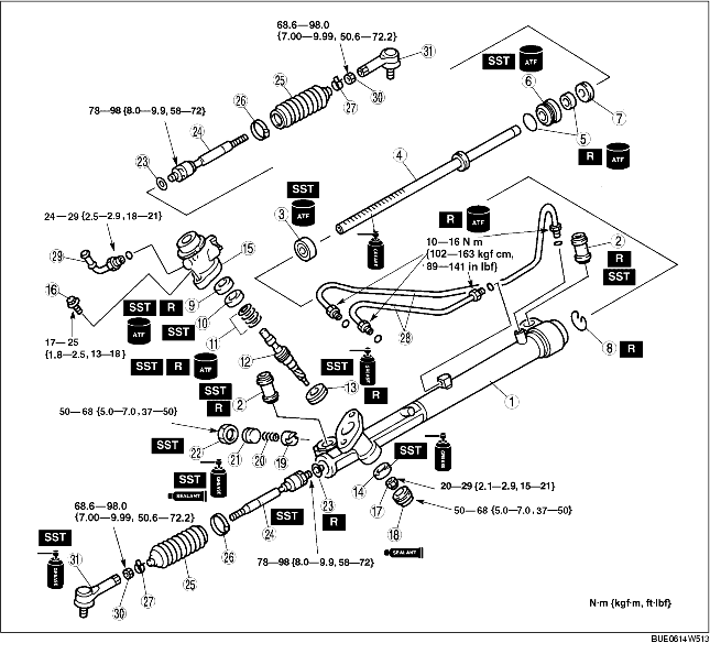
1. Assemble in the order indicated in the table.
2. Apply soapy water to the rubber part of a new mounting bushing.
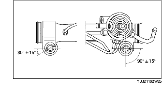
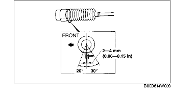
3. Insert the mounting bushing into the gear housing at an angle shown in the figure.
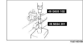
4. Using the SSTs and a press, press the mounting bushing until the mounting bushing end comes out completely from the gear housing.
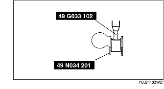
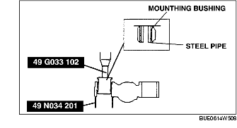
5. Reverse the gear housing, then press the mounting bushing until the mounting bushing end comes out completely from the other side. At this time, assemble the mounting bushing so that the distance between the steel pipe end of the mounting bushing and the gear housing end are as shown in the figure.
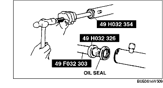
6. Apply power steering fluid to a new oil seal (gear housing). Using the SSTs, assemble the oil seal to the gear housing.
7. After assembly, verify that there is no noise by shaking the gear housing.
8. Apply grease to the steering rack teeth.
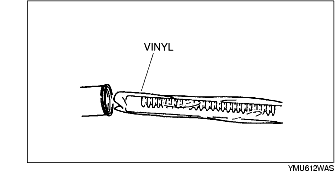
9. Install the vinyl included in the replacement seal kit to the rack teeth and insert the steering rack into the gear housing.
10. Apply power steering fluid to a new oil seal (rack bushing).
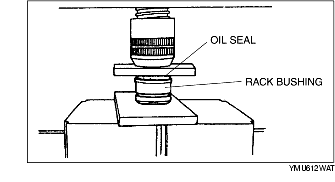
11. Using an appropriate steel plate, press fit the oil seal with a press until the ends of the oil seal and rack bushing become flush with each other.
12. Apply power steering fluid to a new O-ring and assemble to the rack bushing.
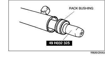
13. After installing the SST to the steering rack end, assemble the rack bushing to the rack housing.
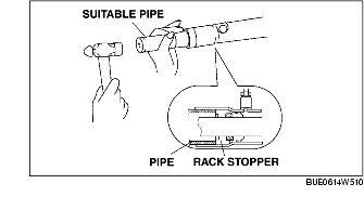
14. Using an appropriate pipe and a hammer, insert the rack stopper into the gear housing until the clip installation groove of the gear housing comes out.
15. Pinch the both ends of the new clip using long-nose pliers and install to the clip installation groove.
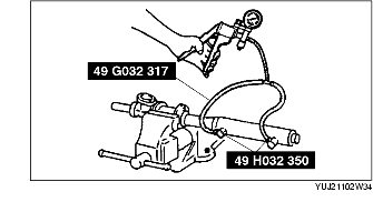
16. Inspect the cylinder for airtightness as follows:
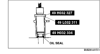
17. Apply power steering fluid to a new oil seal (valve housing).
18. Press fit the oil seal to the valve housing using the SSTs.
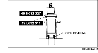
19. Press fit the upper bearing to the valve housing using the SSTs.
20. Apply power steering fluid to a new seal ring.
21. Assemble the seal ring to the pinion shaft component.
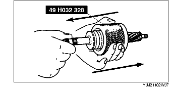
22. Let the pinion shaft component through the SST once from each side and shape the seal ring.
23. Apply grease to a new oil seal (pinion shaft).
24. Assemble the oil seal from the pinion shaft gear side.
25. Assemble the pinion shaft component to the valve housing.
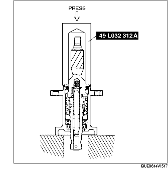
26. Press fit the pinion shaft component and oil seal (pinion shaft) to the valve housing using the SST.
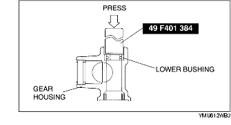
27. Press fit the lower bearing to the gear housing using the SST.
28. Assemble the valve housing component to the gear housing and tighten the bolt.
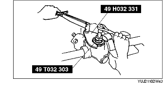
29. Temporarily install the tie rod to the steering rack.
30. Tighten the locknut (housing cover).
31. Apply silicone sealant to the threads of the housing cover and assemble to the gear housing.
32. Apply grease to the steering rack contact surface of the support yoke.
33. Assemble the support yoke and yoke spring to the gear housing.
34. Apply sealant to the threads of the adjusting cover.
35. Assemble the adjusting cover using the SSTs and tighten to 20-29 N·m {2.1-2.9 kgf·m, 15-21 ft·lbf}.
36. Loosen the adjusting cover to approx. 25-30× using the SSTs.
37. Using the SSTs, secure the adjusting cover and tighten the locknut (adjusting cover).
38. Perform the pinion preload adjustment as follows:
39. Assemble a new washer.
40. Secure the rack teeth in a vise via copper plate or a piece of clean rag.
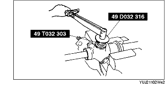
41. Tighten the tie rod using the SST.
42. Crimp the washer.
43. Assemble the boot.
44. Install the boot band to the large end of the boot as shown in the figure.
45. Install a new boot clamp.
46. Inspect the boot for dents or twisting while sliding the rack fully to the left and right.
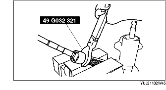
47. Apply power steering fluid to a new O-ring and assemble to the oil pipe and return pipe.
48. Assemble the oil pipe and return pipe to the steering gear.
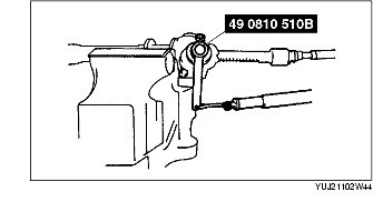
49. Tighten the tie-rod end nut.
50. Assemble the tie-rod end according to the alignment marks made during disassembly and tighten the tie-rod end nut.