PROCEDURES FOR DETERMINING LOCATION OF MALFUNCTION [L3]
id0902h5825700
System Wiring Diagram
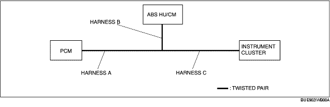
PCM
1. Using the WDS or equivalent, verify that the DTC U0121 is displayed. (See DTC TABLE [MULTIPLE COMMUNICATION SYSTEM (L3)].)
2. Referring to the following table, determine the malfunctioning part of the CAN system.
-
Note
-
• To examine the communication between instrument cluster and ABS HU/CM, use the PID on the instrument cluster side.
|
Module
|
Communication status
|
Malfunctioning part
|
|
ABS HU/CM
|
Instrument cluster
|
|
PCM
|
Error
|
Error
|
• Wiring harness A
• PCM
|
|
Error
|
Normal
|
• Wiring harness B
• ABS HU/CM
|
|
Normal
|
Error
|
• Wiring harness C
• Instrument cluster
|
Instrument cluster
1. Using the WDS or equivalent, verify that DTC U1900 is displayed. (See DTC TABLE [MULTIPLE COMMUNICATION SYSTEM (L3)].)
2. Access and monitor the "PCM_MSG" and "ABS_MSG" PIDs using the WDS or equivalent.
3. Verify the PID. (See PID/DATA MONITOR AND RECORDING PROCEDURE [L3].)
4. Referring to the following table, determine the malfunctioning part of the CAN system.
|
Module
|
Communication status
|
Malfunctioning part
|
|
PCM
|
ABS HU/CM
|
|
Instrument cluster
|
Error
|
Error
|
• Wiring harness C
• Instrument cluster
|
|
Error
|
Normal
|
• Wiring harness A
• PCM
|
|
Normal
|
Error
|
• Wiring harness B
• ABS HU/CM
|
ABS HU/CM
-
Note
-
• The ABS HU/CM does not have any PID for examining communication between the ABS HU/CM and instrument cluster. Therefore, use the PIDs on the instrument cluster side to determine the location of malfunction.
1. Using the WDS or equivalent, verify that DTC U1900 or U2023 is displayed. (See DTC TABLE [MULTIPLE COMMUNICATION SYSTEM (L3)].)
2. Referring to the following table, determine the malfunctioning part of the CAN system.
|
Module
|
Communication status
|
Malfunction location
|
|
PCM
|
Instrument cluster
|
|
ABS HU/CM
|
Error
|
Error
|
• Wiring harness B
• ABS HU/CM
|
|
Error
|
Normal
|
• Wiring harness A
• PCM
|
|
Normal
|
Error
|
• Wiring harness C
• Instrument cluster
|