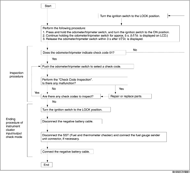
INPUT/OUTPUT CHECK MODE OF INSTRUMENT CLUSTER [L3]


id0922008002a6

Note
• The items in the following chart can be verified using output check mode.

Check Code Table

Check Code

Check Item

Related Item

01
Seat belt warning switch
04
Door lock switch
• Lights-on reminder warning alarm
• Key reminder warning alarm
08
TNS relay
• Lights-on reminder warning alarm
• Each illumination light
12
Speedometer
Speedometer
13
Tachometer
Tachometer
14
Buzzer
Buzzer
15*
Rear fog light
• Rear fog light
• Rear fog indicator light
16
Fuel-level warning light
22
Fuel gauge sender unit (fuel pump unit)
Fuel gauge
23
Fuel gauge
Fuel gauge
25
Water temperature gauge
26
Warning and indicator light controlled by odometer/tripmeter (LCD) and microcomputer
• Odometer/tripmeter
• Warning and indicator light
29*
Rear fog light switch
Rear fog light control
30
Ignition switch (ACC)
31
Key reminder switch
Key reminder warning alarm
40*
Front fog light
Front fog indicator light
56
SAS unit
Air bag warning alarm

* : If equiped
Note
• Check codes which are not listed in the check code table may be indicated, but they cannot be inspected.
• The check codes are displayed in numerical order. (While performing the inspection, if you want to inspect a check code with a number smaller than the code number you are currently inspecting, terminate the check mode then repeat the inspection from the beginning.)
• If a speed signal is input to the instrument cluster (the wheels are rotated), the input/output check mode will be cancelled.
• The check codes can be fast-forwarded by pushing and holding the odometer/tripmeter switch for 1 s or more.

Checking Order

Note
• When checking multiple check codes, begin with the code with highest ranking.

Checking order

Ignition switch position

Check code

1
ON
22
2
04, 08, 12, 13, 14, 16, 18, 23, 25, 26, 28, 55
3
LOCK
30, 31

Check Code Inspection

Check code 01

Check code 01

Seat belt warning switch ON/OFF signal

Step

Inspection condition

Display

Action

1
Driver's side seat belt is unbuckled. (Seat belt retractor switch is ON)

Go to the next step.

Verify that the voltage of instrument cluster terminal 1K is 0 V.
• If the voltage is as specified, replace the instrument cluster.
• If the voltage is not as specified, inspect the following parts:
- Seat belt warning switch
- Wiring harness (seat belt warning switch -instrument cluster)
2
Driver's side seat belt is buckled. (Seat belt retractor switch is OFF)


Verify that the voltage of instrument cluster terminal 1K is B+.
• If the voltage is as specified, replace the instrument cluster.
• If the voltage is not as specified, inspect the following parts:
- Seat belt warning switch
- Wiring harness (seat belt warning switch -instrument cluster)


Input signal to the instrument cluster is normal.

Check code 04

Check code 04

Door lock switch ON/OFF signal

Step

Inspection condition

Display

Action

1
Open the front driver-side door. (Door switch ON)

Close the front driver-side door, then go to the next step.

Verify that the voltage of instrument cluster terminal 2I is 1.0 V or less.
• If the voltage is as specified, replace the instrument cluster.
• If the voltage is not as specified, inspect the following parts:
- Door lock switch
- Wiring harness (instrument cluster - door catch switch)
2
Close the front driver-side door. (Door switch OFF)

Verify that the voltage of instrument cluster terminal 2I is B+.
• If the voltage is as specified, replace the instrument cluster.
• If the voltage is not as specified, inspect the following parts:
- Door lock switch
- Wiring harness (instrument cluster - door catch switch)

Input signal to the instrument cluster is normal.

Check code 08

Check code 08

TNS relay ON/OFF signal

Step

Inspection condition

Display

Action

1
Turn the light switch to the TNS position. (TNS relay ON)

Go to the next step.

Verify that the voltage of instrument cluster terminal 3A is B+.
• If the voltage is as specified, replace the instrument cluster.
• If the voltage is not as specified, inspect the following parts:
- TNS relay
- Wiring harness (Battery-TNS relay-instrument cluster)
2
Turn the light switch off. (TNS relay OFF)

Verify that the voltage of the instrument cluster terminal 3A is 1.0 V or less.
• If the voltage is as specified, replace the instrument cluster.
• If the voltage is not as specified, inspect the following parts:
- TNS relay
- Wiring harness (TNS relay-instrument cluster)

Input signal to the instrument cluster is normal.

Check code 12

Check code 12

Speedometer display signal

Inspection condition

Display

Action

After selecting check code 12, wait for approx. 2 s.

The speedometer needle moves full scale then returns to approx. 60 km/h.
The speedometer is normal.
Except above
Replace the instrument cluster.

-

Check code 13

Check code 13

Tachometer indicator signal

Inspection condition

Display

Action

After selecting check code 13, wait for approx. 2 s.

The tachometer needle moves full scale then returns to approx. 3,000 rpm .
The tachometer is normal.
Except above
Replace the instrument cluster.

-

Check code 14

Check code 14

Buzzer operation signal

Inspection condition

Display

Action

After selecting check code 14, wait for approx. 2 s.

The buzzer sounds.
The buzzer is normal.
The buzzer does not sound.
Replace the instrument cluster.

Check code 15

Check code 15

Rear fog indicator light flashing signal

Inspection condition

Display

Action

After selecting check code 15, wait for approx. 2 s.

The rear fog indicator light flashes 3 times.
The rear fog indicator light is normal.
Except above
Verify that the voltage of instrument cluster terminal 2D is B+.
• If the voltage is as specified, replace the instrument cluster.
• If the voltage is not as specified, inspect the following parts:
- Rear fog light relay
- Wiring harness (Battery-rear fog light-instrument cluster)

Check code 16

Check code 16

Fuel-level warning light flashing signal

Inspection condition

Display

Action

After selecting check code 16, wait for approx. 2 s.

The fuel-level warning light flashes three times.
The fuel-level warning light is normal.
Except above
Replace the instrument cluster.

Check code 22

Preparation

Check code 22

Fuel level signal

Step

Inspection condition

Display

Action

1
Select check code 22 with the fuel gauge sender unit connector disconnected.

Go to the next step.
Except above
Replace the instrument cluster.
2
Connect terminals 2I and 3Q of the instrument cluster.

Go to the next step.
Except above
Replace the instrument cluster.
3
Using the SST (Fuel and thermometer checker) or resistor, input 20 ohms between instrument cluster terminals 2I and 3Q.

Go to the next step.
Except above
Replace the instrument cluster.
4
Using the SST (Fuel and thermometer checker) or resistor, input 60 ohms between instrument cluster terminals 2I and 3Q.

Go to the next step.
Except above
Replace the instrument cluster.
5
Using the SST (Fuel and thermometer checker) or resistor, input 100 ohms between instrument cluster terminals 2I and 3Q.

Inspect the fuel gauge sender unit.
Except above
Replace the instrument cluster.

Check code 23

Check code 23

Fuel gauge operation signal

Inspection condition

Display

Action

After selecting check code 23, wait for approx. 2 s.

The fuel gauge indicates status in the following order approx. every 2 s.
• F → 1/2 → E → F (fixed)
The fuel gauge is normal.
Except above
Replace the instrument cluster.

Replace the instrument cluster.

Check code 25

Check code 25

Water temperature gauge operation signal

Inspection condition

Display

Action

After selecting check code 25, wait for approx. 2 s.

The water temperature gauge indicates status in the following order approx. every 2 s.
• H→Center→C→H (fixed)
The water temperature gauge is normal.
Except above
Replace the instrument cluster.

Replace the instrument cluster.

Check code 26

Check code 26

Odometer/tripmeter display signal

Inspection condition

Display

Action

Select check code 26.

LCD display and warning and indicator light controlled by micro computer are illuminated.
• O/D OFF indicator light
• Malfunction indicator lamp
• Fuel-level warning light
• ABS warning light
• Rear fog indicator light
• Seat belt warning light
• Brake system warning light
• Generator warning light
Odometer/tripmeter is normal, and warning and indicator light is normal.
Except above
Replace the instrument cluster.

Check code 29

Check code 29

Rear fog light switch ON/OFF signal

Step

Inspection condition

Display

Action

1
Press and hold down the rear fog light switch pressed.

Go to the next step.

Verify that the voltage of instrument cluster terminal 2F is B+.
• If the voltage is as specified, replace the instrument cluster.
• If the voltage is not as specified, inspect the following parts:
- Rear fog light switch
- Wiring harness (Rear fog light switch-instrument cluster)
2
Release the rear fog light switch.

Verify that the voltage of instrument cluster terminal 2F is 1.0 V or less.
• If the voltage is as specified, replace the instrument cluster.
• If the voltage is not as specified, inspect the following parts:
- Rear fog light switch
- Wiring harness (Rear fog light switch-instrument cluster)

Input signal to the instrument cluster is normal.

Check code 30

Check code 30

Ignition switch (ACC) ON/OFF signal

Step

Inspection condition

Display

Action

1
Turn the ignition switch to the ACC position.

Go to the next step.

Verify that the voltage of instrument cluster terminal 3M is B+.
• If the voltage is as specified, replace the instrument cluster.
• If the voltage is not as specified, inspect the following parts:
- Ignition switch
- Wiring harness (Battery-ignition switch-instrument cluster)
2
Turn the ignition switch off.

Verify that the voltage of the instrument cluster terminal 3M is 1.0V or less.
• If the voltage is as specified, replace the instrument cluster.
• If the voltage is not as specified, inspect the following parts:
- Ignition switch
- Wiring harness (Ignition switch-instrument cluster)

Input signal to the instrument cluster is normal.

Check code 31

Check code 31

Key reminder switch ON/OFF signal

Step

Inspection condition

Display

Action

1
Turn the light switch to the TNS position.
Remove the key from the steering lock and reinsert the key into the steering lock after selecting check code 31. (Key reminder switch switch ON)

Go to the next step.

Verify that the voltage of instrument cluster terminal 2Q is B+.
• If the voltage is as specified, replace the instrument cluster.
• If the voltage is not as specified, inspect the following parts:
- Key reminder switch (in the ignition switch)
- Wiring harness (Battery-key reminder switch-instrument cluster)
2
Remove the key from the steering lock. (Key reminder switch switch OFF)

Verify that the voltage of instrument cluster terminal 2Q is 1.0 V or less.
• If the voltage is as specified, replace the instrument cluster.
• If the voltage is not as specified, inspect the following parts:
- Key reminder switch (built into ignition switch)
- Wiring harness (Key reminder switch-instrument cluster)

Input signal to the instrument cluster is normal.

Check code 40

Check code 40

Front fog light switch ON/OFF signal

Step

Inspection condition

Display

Action

1
Turn the front fog light switch to the ON position.

Go to the next step.

Verify that the voltage of instrument cluster terminal 2H is B+.
• If the voltage is as specified, replace the instrument cluster.
• If the voltage is not as specified, inspect the following parts:
- Front fog light relay
- Wiring harness (Battery-front fog light relay-instrument cluster)
2
Turn the front fog light switch off.

Verify that the voltage of instrument cluster terminal 2H is 1.0 V or less.
• If the voltage is as specified, replace the instrument cluster.
• If the voltage is not as specified, inspect the following parts:
- Front fog light relay
- Wiring harness (Front fog light relay-instrument cluster)

Input signal to the instrument cluster is normal.

Check code 56

Check code 56

Air bag warning alarm ON/OFF signal

Step

Inspection condition

Display

Action

1
Connect the WDS or equivalent to the DLC-2.
Turn ON the simulation item "WRNLMPCHM" of the SAS unit.

Go to the next step.

Verify that the voltage of the instrument cluster terminal 2J is 1.0 V or less.
• If the voltage is as specified, replace the instrument cluster.
• If the voltage is not as specified, inspect the following parts:
- SAS unit
- Wiring harness (SAS unit-instrument cluster)
2
Turn OFF the simulation item "WRNLMPCHM" of the SAS unit.

Verify that the voltage of instrument cluster terminal 2J is B+.
• If the voltage is as specified, replace the instrument cluster.
• If the voltage is not as specified, inspect the following parts:
- SAS unit
- Wiring harness (SAS unit-instrument cluster)

Input signal to the instrument cluster is normal.