1. Inspect the speedometer using check code "GAGE" of the input/output check mode. (See INPUT/OUTPUT CHECK MODE OF INSTRUMENT CLUSTER [EXCEPT L3].)
1. Adjust the tire pressure to the specification.
2. Using a speedometer tester, verify that the tester reading is as indicated in the table.
|
Speedometer tester indication (km/h)
|
Allowable range (km/h)
|
|---|---|
|
20
|
19-22
|
|
40
|
38-43
|
|
60
|
58-64
|
|
80
|
77-86
|
|
100
|
97-107
|
|
120
|
116-128
|
|
140
|
135-149
|
1. Inspect the tachometer using check code "GAGE" of the input/output check mode. (See INPUT/OUTPUT CHECK MODE OF INSTRUMENT CLUSTER [EXCEPT L3].)
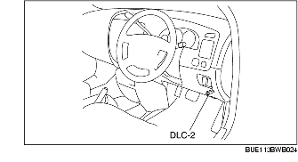
1. Connect the WDS or equivalent to the DLC-2 (16-pin).
2. Compare the data monitor item ISS_SRC of PCM with the tachometer indication.
1. Inspect the fuel gauge using check code "GAGE"of the input/output check mode. (See INPUT/OUTPUT CHECK MODE OF INSTRUMENT CLUSTER [EXCEPT L3].)
1. Inspect the water temperature gauge using check code "GAGE" of the input/output check mode. (See INPUT/OUTPUT CHECK MODE OF INSTRUMENT CLUSTER [EXCEPT L3].)