Fuel and Emissions System Description - PGM-FI System
Fuel and Emissions System Description - PGM-FI System
PGM-FI System
The programmed fuel injection (PGM-FI) system is a sequential multiport fuel injection system.
Air Conditioning (A/C) Compressor Clutch Relay
When the PCM receives a demand for cooling from the A/C system, it delays the compressor from being energized, and enriches the mixture to assure a smooth transition to the A/C mode.
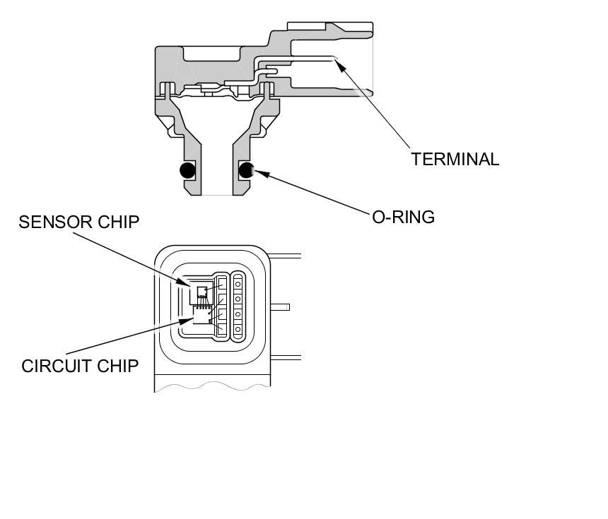
Air Fuel Ratio (A/F) Sensor
The A/F sensor operates over a wide mixture range. The A/F sensor is installed upstream of the warm up three way catalytic converter (WU-TWC), and it sends signals to the PCM which varies the duration of fuel injection accordingly.

Barometric Pressure (BARO) Sensor
The BARO sensor is inside the PCM. It converts atmospheric pressure into a voltage signal that is used by the PCM to modify the basic duration of the fuel injection discharge.
Camshaft Position (CMP) Sensor B
The CMP sensor B detects the position of the No. 1 cylinder as a reference for sequential fuel injection to each cylinder.

Crankshaft Position (CKP) Sensor
The CKP sensor detects crankshaft speed and is used by the PCM to determine ignition timing, timing for fuel injection of each cylinder, and engine misfire detection.

Engine Coolant Temperature (ECT) Sensors 1 and 2
ECT sensors 1 and 2 are temperature dependent resistors (thermistors). The resistance decreases as the engine coolant temperature increases.
ECT sensor 1 is on the cylinder head, and ECT sensor 2 is on the radiator.
ECT sensor 1

ECT sensor 2

Ignition Timing Control
The PCM contains the memory for basic ignition timing at various engine speeds and manifold absolute pressure. It also adjusts the timing according to engine coolant temperature and intake air temperature.
Injector Timing and Duration
The PCM contains the memory for basic discharge duration at various engine speeds and manifold pressures. The basic discharge duration, after being read out from the memory, is further modified by signals sent from various sensors to obtain the final discharge duration.
By monitoring short term fuel trim (ST FUEL TRIM), the PCM detects long term malfunctions in the fuel system and sets a diagnostic trouble code (DTC) if needed.
Intake Air Temperature (IAT) Sensor 2
IAT sensor 2 is a temperature dependent resistor (thermistor). The resistance of the thermistor decreases as the intake air temperature increases.

Knock Sensor
The knock control system adjusts the ignition timing to minimize knock.

Manifold Absolute Pressure (MAP) Sensor
The MAP sensor converts manifold absolute pressure into electrical signals to the PCM.
Malfunction Indicator Lamp (MIL) Indication (In relation to Readiness Codes)
The vehicle has certain readiness codes that are part of the on-board diagnostics for the emissions systems. If the vehicle's battery has been disconnected or gone dead, if DTCs have been cleared, or if the PCM has been reset, these codes are reset. In some states, part of the emissions testing is to make sure these codes are set to complete. If all of them are not set to complete, the vehicle may fail the test, or the test cannot be finished.
To check if the readiness codes are set to complete, turn the ignition switch to ON (II), but do not start the engine. The MIL will come on for 15-20 seconds. If it then goes off, the readiness codes are complete. If it flashes five times, one or more readiness codes are not complete. To set each code, drive the vehicle or run the engine as described in the procedures.
Mass Air Flow (MAF) Sensor/Intake Air Temperature (IAT) Sensor 1
MAF sensor/IAT sensor 1 contains a hot wire, a cold film, and a thermistor. It is located in the intake air passage. The resistance of the hot wire, the cold film, and the thermistor changes due to intake air flow and air temperature. The control circuit in the MAF sensor controls the current to keep the hot wire at a set temperature. The current is converted to voltage in the control circuit, then output to the PCM.

Output Shaft (Countershaft) Speed Sensor
This sensor detects output shaft (countershaft) speed.

Secondary Heated Oxygen Sensor (Secondary HO2S)
The secondary HO2S detects the oxygen content in the exhaust gas downstream of the warm up three way catalytic converter (WU-TWC), and sends signals to the PCM which varies the duration of fuel injection accordingly. To stabilize its output, the sensor has an internal heater. The PCM compares the HO2S output with the A/F sensor output to determine catalyst efficiency. The secondary HO2S is located on the WU-TWC.
