A/T Shift Solenoid Valve Test, Replacement, and Shift Solenoid Wire Harness Replacement
A/T Shift Solenoid Valve Test, Replacement, and Shift Solenoid Wire Harness Replacement
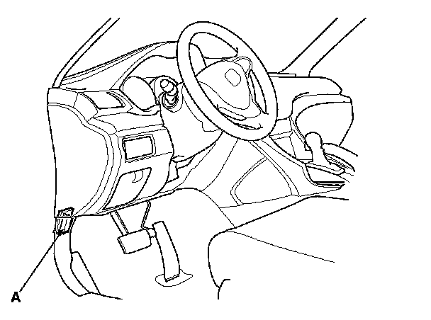
1. Connect the HDS to the DLC (A) located under the driver's side of the dashboard.
2. Turn the ignition switch to ON (II). Make sure the HDS communicates with the PCM. If it does not, go to the DLC circuit troubleshooting. Testing and Inspection
3. Select Shift Solenoid Valves A, B, C, D, or E in the Miscellaneous Test Menu on the HDS.
4. Check that shift solenoid valves A, B, C, D, or E operate with the HDS. A clicking sound should be heard.
- If a clicking sound is heard, the valves are OK. The test is complete, disconnect the HDS.
- If no clicking sound is heard, go to step 5.
5. Raise the vehicle on a lift, or apply the parking brake, block the rear wheels, and raise the front of the vehicle. Make sure it is securely supported.
6. Remove the splash shield.
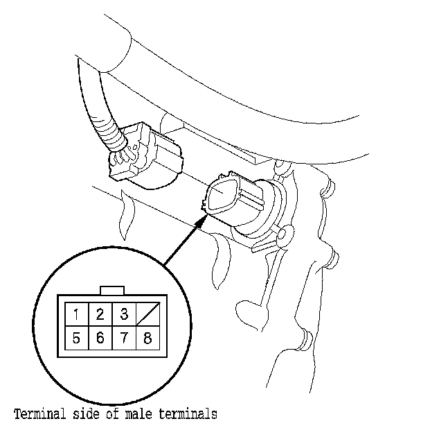
7. Disconnect the shift solenoid wire harness connector.
8. Measure the resistance between each of the following terminals and body ground.
- No. 1 terminal: Shift solenoid valve C
- No. 2 terminal: Shift solenoid valve B
- No. 3 terminal: Shift solenoid valve E
- No. 5 terminal: Shift solenoid valve A
- No. 8 terminal: Shift solenoid valve D

- If the resistance is within the standard, go to step 9.
- If the resistance is out of standard, go to step 10.
9. Connect a jumper wire from the battery positive terminal to each shift solenoid wire harness connector terminal individually. A clicking sound should be heard.
- If a clicking sound is heard, the valves are OK, and the test is complete, reconnect the connector.
- If no clicking sound is heard, go to step 10.
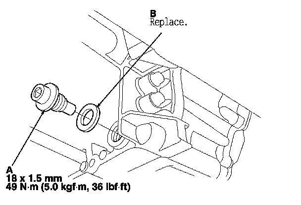
10. Remove the drain plug (A), and drain the ATF.
11. Reinstall the drain plug with a new sealing washer (B).
12. Do the battery removal procedure. Removal and Replacement
13. Disconnect PCM connectors A, B, and C, then remove the PCM. Service and Repair
14. Remove the battery base. Service and Repair
15. Remove the intake air duct. Service and Repair
16. Remove the left front wheel.
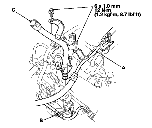
17. Remove the ATF dipstick, and remove the bolts securing the ATF cooler line (A). Remove the harness clamp (B), then remove the ATF dipstick guide tube (C).
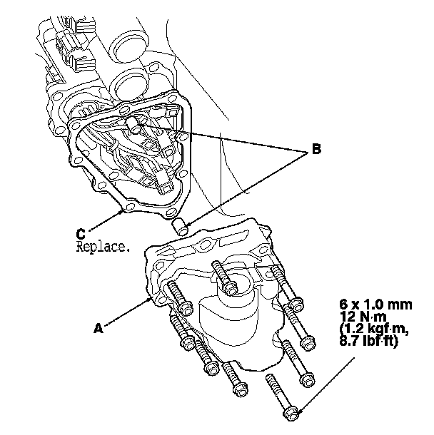
18. Remove the shift solenoid valve cover (A), the dowel pins (B), and the gasket (C).
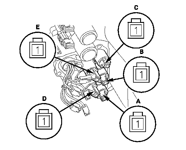
19. Disconnect the shift solenoid valve connectors.
20. Measure the resistance of each shift solenoid valve between the connector terminals and body ground.

- If the resistance is within the standard, go to step 21.
- If the resistance is out of standard, go to step 23.
21. Connect a jumper wire from the negative battery terminal to body ground, and connect another jumper wire from the positive battery terminal to each shift solenoid valve terminal individually.
- If a clicking sound is heard, go to step 22.
- If no clicking sound is heard, go to step 23.
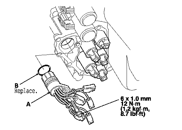
22. Remove the bolt securing the shift solenoid wire harness (A), replace the shift solenoid wire harness and the O-ring (B), then go to step 29.
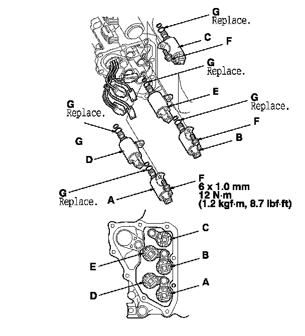
23. Remove the shift solenoid valve mounting bolts (F), then hold the shift solenoid valve body, and remove the shift solenoid valves.
NOTE: Do not hold the shift solenoid valve connector to remove the shift solenoid valves.
24. Install new O-rings (two O-rings per shift solenoid valve) (G) on the shift solenoid valves.
NOTE: A new shift solenoid valve comes with new O-rings. If you install a new shift solenoid valve, use the O-rings provided with it.
25. Install shift solenoid valve C (brown connector), shift solenoid valve D (black connector), and shift solenoid valve E (black connector) by holding the shift solenoid valve body; make sure the mounting bracket contacts the servo body.
NOTE: Do not hold the shift solenoid valve connector to install the shift solenoid valve. Be sure to hold the shift solenoid valve body.
26. Install shift solenoid valve A (brown connector) by holding the shift solenoid valve body; make sure the mounting bracket contacts the bracket of shift solenoid valve D.
NOTE: Do not install shift solenoid valve A before installing shift solenoid valve D. If shift solenoid valve A is installed before installing shift solenoid valve D, it may damage the hydraulic control system.
27. Install shift solenoid valve B (brown connector) by holding the shift solenoid valve body; make sure the mounting bracket contacts the bracket of shift solenoid valve E.
NOTE: Do not install shift solenoid valve B before installing shift solenoid valve E. If shift solenoid valve B is installed before installing shift solenoid valve E, it may damage the hydraulic control system.
28. Install the shift solenoid valve mounting bolts.
29. Connect the shift solenoid valve connectors:
- BLU wire connector to shift solenoid valve A.
- ORN wire connector to shift solenoid valve B.
- GRN wire connector to shift solenoid valve C.
- YEL, WHT, and WHT wire connector to shift solenoid valve D.
- RED wire connector to shift solenoid valve E.
30. Install a new gasket, the dowel pins, and the shift solenoid valve cover.
31. Install a new O-ring on the ATF dipstick guide tube, then install the guide tube with the bolts.
32. Check the shift solenoid wire harness connector for rust, dirt, or oil, and clean or repair if necessary. Then connect the connector securely.
33. Secure the ATF cooler line with the bolts.
34. Install the harness clamp on its bracket.
35. Install the intake air duct. Service and Repair
36. Install the battery base. Service and Repair
37. Connect PCM connectors A, B, and C, then install the PCM. Service and Repair
38. Do the battery installation procedure. Removal and Replacement
39. Install the splash shield.
40. Install the left front wheel.
41. Refill the transmission with ATF. ATF Replacement