Throttle Position Sensor: Testing and Inspection
Throttle Position (TP) Sensor, Checking
NOTE: Throttle Position (TP) sensor -G69- is located inside the throttle valve control module -J338-.
Test conditions
- Throttle valve in closed throttle position; if necessary adjust accelerator pedal cable
- Cruise control adjustment OK
- Power supply for throttle valve control module OK; Refer to "Throttle Valve Control Module Power Supply, Checking" Testing and Inspection
Checking
- Connect VAG 1551 or VAG 1552 scan tool and press buttons -0- and -1- to insert "Engine Electronics" address word 01 (with ignition switched; engine not running).Refer to "Scan Tool Testing/Scan Tool Connecting and Initial Checks/Connecting VAG 1551/1552 Scan Tool" Testing and Inspection
Indicated on display
Rapid data transfer HELP
Select function XX
- Press buttons -0- and -8- to select "Read Measuring Value Block" function 08, and press -Q- button to confirm input.
Indicated on display
Read Measuring Value Block HELP
Input display group number XXX
- Open throttle valve slowly while monitoring degree ( ° ) value in display field 3.
Value must increase uniformly over the entire range.
- Press -> button to advance program sequence.
- Press buttons -0-, -0- and -3- to input display group number 3, and press -Q- button to confirm input.
Indicated on display (1-4 = display fields)
Read Measuring Value Block 3 ->
1 2 3 4
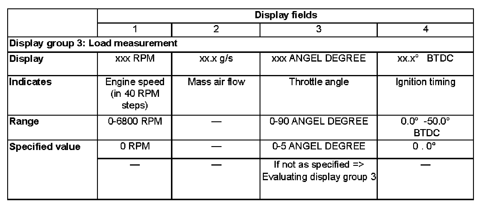
- Compare display with specified values for throttle angle,display field 3):
Display Group 3:
- Press buttons -0- and -6- to select "End Output" function 06, and press -Q- button to confirm input.
- Switch ignition off.
NOTE: The values displayed in display field 3 depend on the calibration of the Throttle Position (TP) sensor and do not correspond with the actual throttle valve opening in degrees. The maximum displayed value is 90.0 Angle Degree.
If the throttle angle value does not increase uniformly:
- Replace throttle valve control module -J338-.
- Carry out adaptation of throttle valve control module to ECM.
- Check readiness code. If Diagnostic Trouble Code (DTC) memory has been erased, or ECM was disconnected, generate new readiness code.
Refer to "Monitors, Trips and/or Drive Cycle/Displaying Readiness Code" Testing and Inspection
Refer to "Monitors, Trips and/or Drive Cycle/Generating Readiness Code" Testing and Inspection
Evaluating display group 3
Display Field 3:
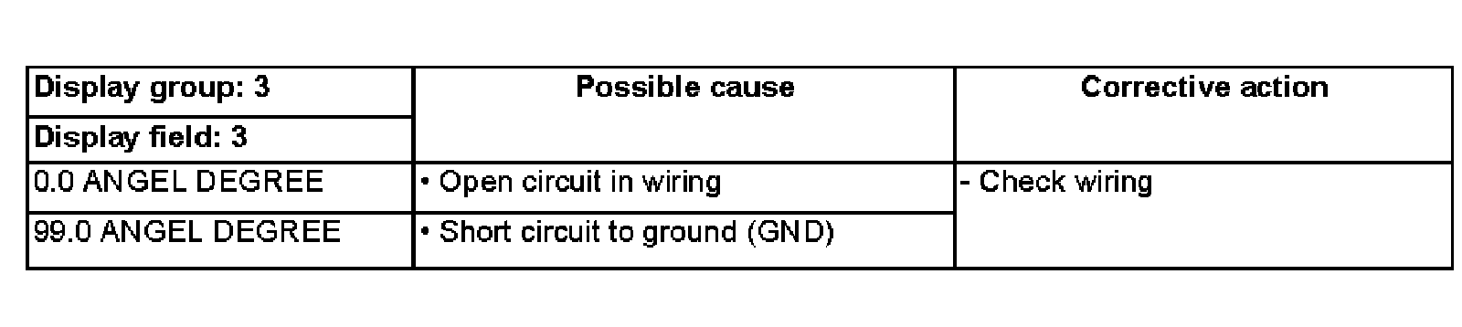
Checking wiring
- Connect VAG 1598/22 test box to ECM harness connector. Refer to "Scan Tool Testing/Scan Tool Connecting and Initial Checks/Connecting VAG 1598/22 Test Box" Testing and Inspection
- Connect multimeter US 1119 (Fluke 83 or equivalent), using adapter cables from VW 1594 connector test kit.
- Measure resistance to check for short circuit between test box sockets 2 (Ground) and 75 (signal wire).
- Test box sockets 2 and 75
- Specified value: Infinity Ohms
- Switch multimeter to voltage (20 VDC) measuring range.
- Switch ignition on.
- Check wiring for short circuit to B+.
Note voltage reading if applicable (if not 0 volts).
- Switch ignition off.
- Continue test, depending on whether or not voltage was measured.
Continuation (with measured voltage)

- Disconnect 8-pin harness connector from throttle valve control module -J338-.
If measured voltage was approx. 5 volts:
- Connect multimeter US 1119 (Fluke 83 or equivalent), using adapter cables from VW 1594 connector test kit.
- Measure resistance to check for short circuit between test box sockets 62 (power supply) and 75 (signal wire).
- Test box sockets 62 and 75
- Specified value: Infinity Ohms
If measured voltage was approx. battery positive voltage (B+):
- Check wiring at 8-pin connector, terminal 5 for short circuit to battery B+.
Continuation (with no measured voltage)
- Disconnect 8-pin harness connector from throttle valve control module -J338-.
- Check wiring for open circuit between ECM/test box and 8-pin harness connector.
- Connector terminal 5 to ECM/test box socket 75
- Specified value: max. 1.5 Ohms
If wiring is OK:
- Replace throttle valve control module -J338-.
- Carry out adaptation of throttle valve control module to ECM.
- Check readiness code. If Diagnostic Trouble Code (DTC) memory has been erased, or ECM was disconnected, generate new readiness code.
Refer to "Monitors, Trips and/or Drive Cycle/Displaying Readiness Code" Testing and Inspection
Refer to "Monitors, Trips and/or Drive Cycle/Generating Readiness Code" Testing and Inspection