With Generic Scan Tool
Intake Air Temperature (IAT) sensor, checking
Recommended special tools and equipment
- VAG 1526 multimeter or VAG 1715 multimeter
- VAG 1594 connector test kit
- Wiring diagram
- Chilling spray (commercially available)
Test requirements

- The respective fuses of Motronic Engine Control Module (ECM) -J220- must be OK.
- Parking brake must be engaged or else daylight driving lights will be switched on.
Function test
- Connect diagnostic tester.
- Switch ignition on.
- Under address word 33, select "Diagnostic mode 1: Checking measuring values."
- Select the measuring value "PID 15: Intake air temperature".
- Check specified value of intake air temperature:
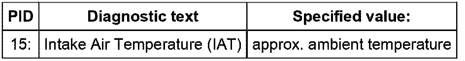
If specified value is not obtained:
- Continue test according to the following table:
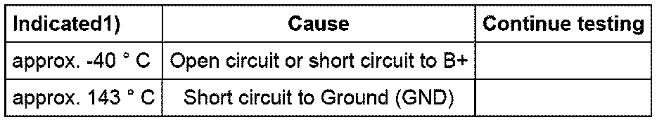
1) If a temperature is indicated which is below the ambient temperature of sensor, first check sensor wires for contact resistance. Note that while the vehicle is standing still the sensor might warm up due to radiant heat.
If specified value is obtained:
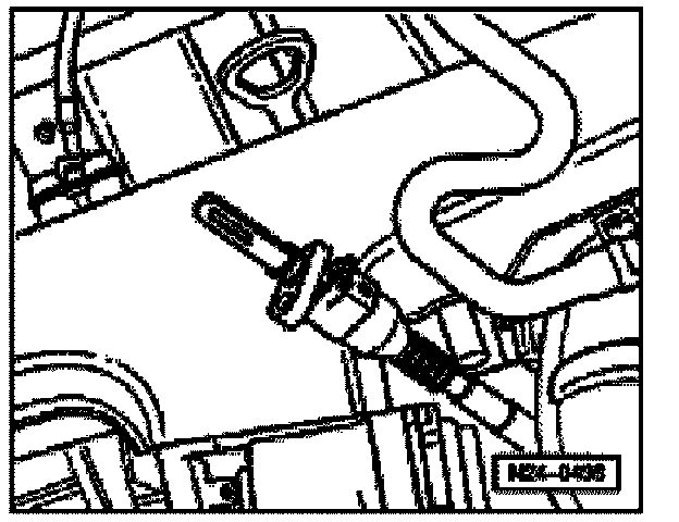
- Remove Intake Air Temperature (IAT) Sensor -G42-. Plug connector back in.
- Remember the intake air temperature value.
- Spray the sensor with commercially available chilling spray while observing the temperature value. The temperature should decrease.
- End diagnosis and switch ignition off.
If the intake air temperature does not drop:
- Replace Intake Air Temperature (IAT) sensor -G42-.
- Erase DTC memory of Engine Control Module (ECM).
- Generate readiness code.
Continuation of test if indication is approx. -40 ° C:

- Disconnect connector -1- from Intake Air Temperature (IAT) Sensor -G42- -2-.
- Bridge terminals 1 & 2 of connector using the respective adapter cables while observing the indication on display.
If indication jumps to approx. 143 � C:
- End diagnosis and switch ignition off.
- Replace Intake Air Temperature (IAT) sensor -G42-.
- Erase DTC memory of Engine Control Module (ECM).
- Generate readiness code.
If indication remains at approx. -40 � C:
- End diagnosis and switch ignition off.
- Check wires according to wiring diagram.
Continuation of test if indication is approx. 143 � C:
- Disconnect connector -1- from Intake Air Temperature (IAT) Sensor -G42- -2-.
If indication jumps to approx. -40 � C:
- End diagnosis and switch ignition off.
- Replace Intake Air Temperature (IAT) sensor -G42-.
- Erase DTC memory of Engine Control Module (ECM).
- Generate readiness code.
If indication remains at approx. 143 � C:
- End diagnosis and switch ignition off.
- Check wires according to wiring diagram.
Checking wiring
- Connect test box to control module wiring harness.

- Check wires between test box and 2-pin connector for open circuit according to wiring diagram.
Terminal 1 & socket 54
Terminal 2 & socket 67
Wire resistance: max: 1.5 Ohms
- Also check wires for short circuits to each other, to vehicle Ground (GND) and to B+.
Specified value: Infinity Ohms
If no wiring faults are found:
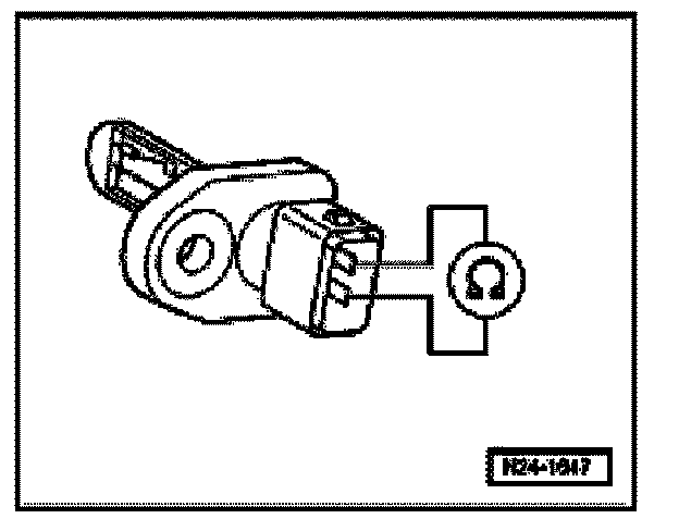
- Measure resistance at Intake Air Temperature (IAT) Sensor -G42-.
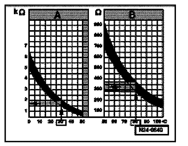
Range A displays resistance values for the temperature range of 0 to 50 � C, range B displays resistance values for the temperature range of 50 to 100 � C.
Read-out examples:
- 30 � C is in range A and corresponds to a resistance of 1.5 to 2.0 k Ohms
- 80 � C is in range B and corresponds to a resistance of 275 to 375 Ohms
If specified value is not obtained:
- Replace Intake Air Temperature (IAT) sensor (G42).
- Erase DTC memory of Engine Control Module (ECM).
- Generate readiness code.
If no malfunctions are detected in the wires and the resistance values are OK:
- Replace Motronic Engine Control Module (ECM) -J220-.