Steering Column, Removing and Installation
Non-Manually Adjustable Steering Column, Steering Column, Removing and Installation
The steering column is supplied as an assembly through the Parts supplier. The steering column is serviced by replacement only.
The ignition lock from the faulty steering column can be refitted , Refer To Starting and Charging.
WARNING:
- Before removing the steering wheel:
- Observe all safety precautions before starting work on any part of the airbag system.
- Disconnect the battery Ground (GND) strap.
- With wheels in the straight-ahead position, unplug the single-pin connector for the airbag system power supply.
Non compliance with the above can cause failure of the airbag system.
Notes:
- Removing and installing driver's-side airbag unit.
- Check Diagnostic Trouble Code (DTC) memory for the airbag system before unplugging the single-pin connector. Refer to Restraint Systems

The red single-pin connector for the airbag system power supply is located on the right behind the instrument panel cover.
- Open front passenger door, remove cover and disconnect single-pin connector.

- Unbolt airbag unit from behind at left and right sides of steering wheel using T30 Torx bit.
Tightening torque: 7 Nm (62 inch lbs.)
WARNING: Always observe the safety precautions for airbag systems when performing any work on the components of the airbag system.
- Carefully fold back airbag unit.

- Disconnect harness connector from airbag unit and place airbag unit aside.
- Unbolt steering wheel; when doing this, make sure that spiral spring is not twisted.
- Remove storage shelf on driver's side.
- Remove steering column switch together with trim.
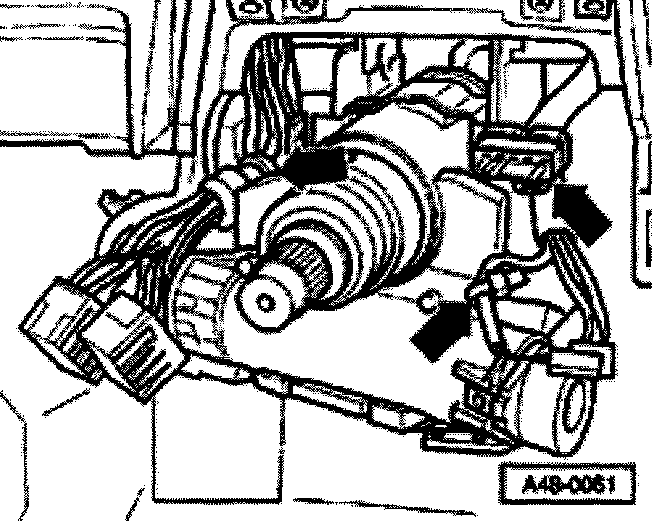
- Remove all tie wraps (arrows) and disconnect harness connectors.
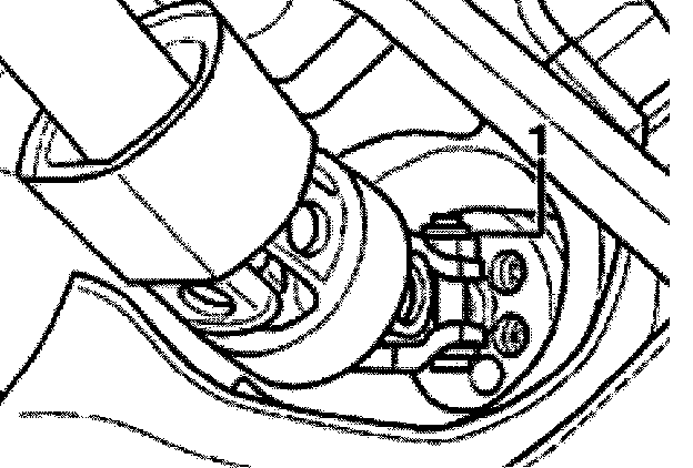
Disengaging lock cable
On vehicles equipped with an automatic transmission, the lock cable must be disengaged:
- Place transmission selector lever in Park position.
- Turn ignition key to position -B- (ignition ON).
- Lift locking clip -1- slightly and remove Bowden cable -2- from steering lock housing.
Securing steering column prior to removal

- Route safety wire through hole in bottom part of steering column (arrow) and spring to secure top and bottom parts of steering column before removing steering column from steering gear pinion.
The steering column can also be secured with a transportation safeguard.
CAUTION:
- The splines between the top and bottom parts of the steering column must not be separated. If the two halves are separated and reassembled with the splines no longer in their origins/ installed positions a rattling noise may result.
- Turn the steering wheel to the center position and do not after position during repairs, otherwise the airbag unit spire/ spring may be damaged.
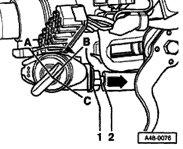
- Unscrew nut -1- at universal joint.
- To release eccentric, turn bolt (Torx T50) clockwise and remove.
- Remove universal joint from steering gear pinion.
- Remove socket head bolts -1- and remove steering column.
Removing and installing steering lock housing, refer to Steering Column Service and Repair.
Installing

1. Locking clip
2. Plastic rod
3. Steering column
New replacement steering columns are supplied with a transportation safeguard installed. This safeguard must be removed after installing the steering column in the vehicle.
Note: It is recommended to save the transportation safeguard components for subsequent steering column removals.
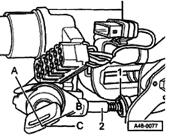
Installing

- When installing steering column, always make sure that cap -1- is installed.
CAUTION: Cap -1- must always be reinstalled or retrofitted' otherwise the electrical wiring may become chafed.
- Mount steering column onto crossmember with four socket-head bolts -1-.
- Attach universal joint to steering gear pinion.
- Insert clamping bolt (Torx T50) through bottom part and engage by turning counterclockwise. Install nut + washer and tighten to 40 Nm (30 ft. lbs.).
CAUTION: The splines between the top and bottom parts of the steering column must not be separated. If the two halves are separated and reassembled with the splines no longer in their original installed positions a rattling noise may result.
Engaging lock cable on vehicles with automatic transmission
- Ignition key must be in position -B- (ignition ON) to engage lock cable
- Move selector lever to park position.
- Insert lock cable -2- into steering lock housing.
- Make sure locking clip -1- engages.
Checking function of lock cable
Applies only to vehicles with automatic transmission.
- Turn ignition key to position -B- (ignition ON).
- It must be possible to move selector shift lever smoothly out of Park position
- It must only be possible to remove ignition key with selector lever in Park position
- Move selector lever to park position.
- Ignition lock must function smoothly
- It must not be possible to move selector lever with ignition key in position -A- (ignition OFF). Ignition key can be removed
Installing, continued for all vehicles
- Remove safety wire between top and bottom parts of steering column.
- Install steering column switch with trim.
- Align steering column relative to trim and make sure joints (gaps) are even
- Tighten socket-head bolts -1-.
Tightening torque: 22.5 Nm (17 ft. lbs.)
- Install storage shelf on driver's side.
- Install steering wheel and airbag unit:
WARNING:
- Make sure that no person is in the vehicle when re-connecting the battery ground strap.
- Observe all safety precautions.