3.2L BKH
Engine Management System
3.2L BKH
3.2L BKH Engine Compartment - Right (Components A - C
are not shown in the overview)
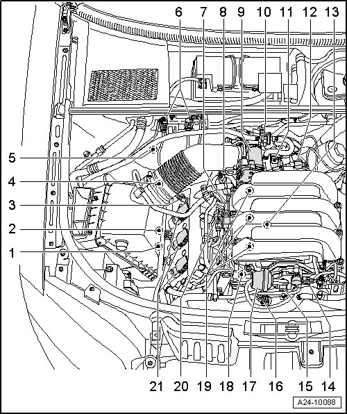
A - Oil Pressure Switch -F1- => [ Oil Pressure Switch ] See Image Below.
B - Oil Level Thermal Sensor -G266- => [ Oil Pan Lower Section ] See Image Below.
• Located at the bottom of lower oil pan
C - Leak Detection Pump (LDP) -V144- => [ EVAP Canister/Leak Detection System Overview ] See Image Below.
• Located in the left rear wheel housing behind wheel housing liner
1 - Right Electro-Hydraulic Engine Mount Solenoid Valve -N145- => [ Left Electro-Hydraulic Engine Mount Solenoid Valve or Right Electro-Hydraulic Engine Mount Solenoid Valve ] See Image Below.
• Located on the right engine mount
• Only on vehicles with automatic transmission
2 - Camshaft Position (CMP) Sensor 3 -G300- => [ Valve for Camshaft Adjustment Bank 1 ] See Image Below.
3 - Camshaft Adjustment Valve 1 -N205- => [ Valve for Camshaft Adjustment Bank 1 ] See Image Below.
4 - Heated Oxygen Sensor (HO2S) -G39- => [ 3.2L BKH Exhaust System ] Locations
5 - Oxygen Sensor (O2S) Behind Three Way Catalytic Converter (TWC) -G130- => [ 3.2L BKH Exhaust System ] Locations
6 - Right Holder for Connectors
7 - Low Fuel Pressure Sensor -G410- => [ Low Fuel Pressure Sensor ] See Image Below.
• Located on the right cylinder head
8 - Camshaft Adjustment Valve 1 (exhaust) -N318- => [ Valve for Camshaft Adjustment Bank 1 ] See Image Below.
9 - Throttle Valve Control Module -J338- => [ Intake Manifold Upper Section Component Overview ] See Image Below.
• Integrated with Throttle Drive (for Electronic Power Control (EPC)) -G186- , Throttle Drive Angle Sensor 1 (for Electronic Power Control (EPC) -G187- and Throttle Drive Angle Sensor 2 (for Electronic Power Control (EPC) -G188-
3.2L BKH Engine Compartment - Right continued
10 - Evaporative Emission (EVAP) Canister Purge Regulator Valve 1 -N80- => [ Evaporative Emission (EVAP) Canister Purge Regulator Valve ] See Image Below.
11 - Intake Air Temperature (IAT) Sensor -G42- and Manifold Absolute Pressure (MAP) Sensor -G71- => [ Intake Manifold Upper Section Component Overview ] See Image Below.
12 - Intake Manifold Runner Control (IMRC) Valve -N316- => [ Intake Manifold Upper Section Component Overview ] See Image Below.
13 - Knock Sensor 1 -G61- => [ Intake Manifold Cylinder Bank 1 (Right) ] See Image Below.
14 - Intake Manifold Tuning (IMT) Valve Position Sensor -G513- => [ Intake Manifold Upper Section Component Overview ] See Image Below.
15 - Intake Manifold Flap Change-over Valve -N239- => [ Intake Manifold Upper Section Component Overview ] See Image Below.
16 - Engine Coolant Temperature (ECT) Sensor -G62- => [ Component Location Front on Engine ] See Image Below.
17 - Actuator for Intake Manifold Change-Over
18 - Intake Manifold Runner Position Sensor -G336- => [ Valve for Camshaft Adjustment Bank 1 ] See Image Below.
19 - Fuel Injectors - Cylinder Bank 1- -N30-, -N31- and -N32- => [ Intake Manifold Cylinder Bank 1 (Right) ] See Image Below.
• Fuel Injectors -Cylinder Bank 2- -N33-, -N83- and -N84- location
20 - Camshaft Position (CMP) Sensor -G40- => [ Valve for Camshaft Adjustment Bank 1 ] See Image Below.
21 - Ignition Coils -Cylinder Bank 1- -N70-, -N127- and -N291-
• Ignition Coils -Cylinder Bank 2- -N292-, -N323- and -N324- location
3.2L BKH Engine Compartment - Left
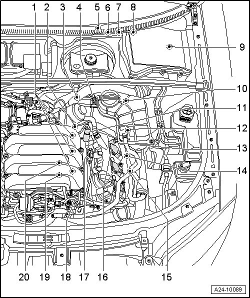
1 - Fuel Injectors -Cylinder Bank 2- -N33-, -N83- and -N84- => [ Intake Manifold Cylinder Bank 2 (Left) ] See Image Below.
2 - Intake Manifold Runner Position Sensor 2 -G512- => [ Intake Manifold Cylinder Bank 2 (Left) ] See Image Below.
3 - Engine Speed (RPM) Sensor -G28- => [ Engine Speed (RPM) Sensor ] See Image Below.
• Located at the front left of transmission housing
4 - Left Holder for Connectors
5 - Instrument Cluster
6 - Throttle Position (TP) Sensor -G79- and Accelerator Pedal Position Sensor 2 -G185- => [ Accelerator Pedal Module ] Locations
• In accelerator pedal module
7 - Brake Light Switch -F- , Brake Pedal Switch -F47- and Clutch Pedal Switch -F36- => [ Brake Light Switch/Brake Pedal Switch and Clutch Pedal Switch ] See Image Below.
• Located at the brake pedal bracket
8 - Clutch Pedal Starter Interlock Switch -F194- => [ Clutch Pedal Starter Interlock Switch ] See Image Below.
9 - SIMOS Control Module -J361- => [ SIMOS Control Module ] See Image Below.
• Located in the E-box plenum chamber
10 - Oxygen Sensor (O2S) 2 Behind Three Way Catalytic Converter -G131- => [ 3.2L BKH Exhaust System ] Locations
3.2L BKH Engine Compartment - Left continued
11 - Camshaft Adjustment Valve 2 -N208- => [ Valve for Camshaft Adjustment Bank 2 ] See Image Below.
12 - Heated Oxygen Sensor (HO2S) 2 -G108- => [ 3.2L BKH Exhaust System ] Locations
13 - Camshaft Adjustment Valve 2 (exhaust) -N319- => [ Valve for Camshaft Adjustment Bank 2 ] See Image Below.
14 - Camshaft Position (CMP) Sensor 4 -G301- => [ Valve for Camshaft Adjustment Bank 2 ] See Image Below.
15 - Left Electro-Hydraulic Engine Mount Solenoid Valve -N144- => [ Left Electro-Hydraulic Engine Mount Solenoid Valve or Right Electro-Hydraulic Engine Mount Solenoid Valve ] See Image Below.
• Located on the left engine mount
• Only vehicles with automatic transmission
16 - Ignition Coils -Cylinder Bank 2- -N292-, -N323- and -N324-
17 - Camshaft Position (CMP) Sensor 2 -G163- => [ Valve for Camshaft Adjustment Bank 2 ] See Image Below.
18 - High Pressure Pump
• With Fuel Metering Valve -N290- => [ High Pressure Pump ] See Image Below.
19 - Fuel Pressure Sensor -G247- => [ Intake Manifold Cylinder Bank 2 (Left) ] See Image Below.
20 - Knock Sensor 2 -G66- => [ Intake Manifold Cylinder Bank 2 (Left) ] See Image Below.
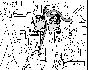
Left Electro-Hydraulic Engine Mount
Solenoid Valve or Right Electro-Hydraulic Engine Mount Solenoid Valve
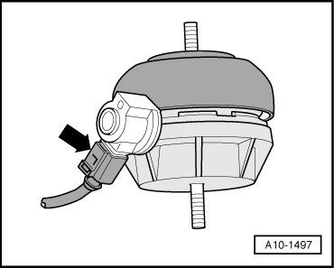
Arrow - Left Electro-Hydraulic Engine Mount Solenoid Valve -N144- or Right Electro-Hydraulic Engine Mount Solenoid Valve -N145-
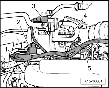
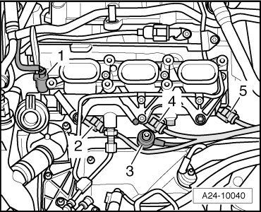
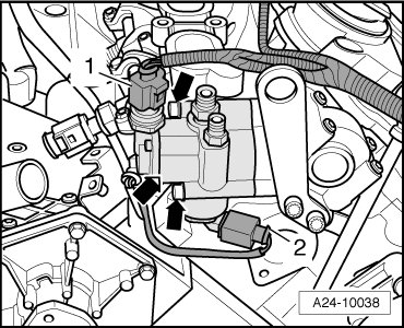
Valve for Camshaft Adjustment
Bank 1
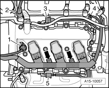
1 - Camshaft Adjustment Valve 1 (exhaust) -N318-
2 - Camshaft Adjustment Valve 1 -N205-
3 - Camshaft Position (CMP) Sensor -G40-
4 - Intake Manifold Runner Position Sensor -G336-
5 - Camshaft Position (CMP) Sensor 3 -G300-
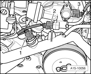
Valve for Camshaft Adjustment Bank
2
1 - Camshaft Position (CMP) Sensor 2 -G163-
2 - Camshaft Adjustment Valve 2 -N208-
3 - Camshaft Adjustment Valve 2 (exhaust) -N319-
4 - Camshaft Position (CMP) Sensor 4 -G301-
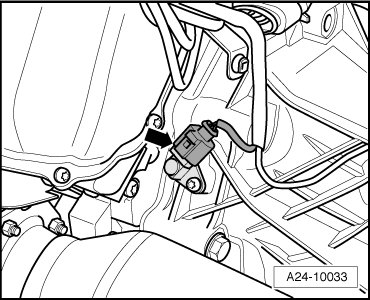
Low Fuel Pressure Sensor
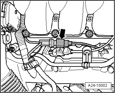
Arrow - Low Fuel Pressure Sensor -G410-
Intake Manifold Upper Section
Component Overview
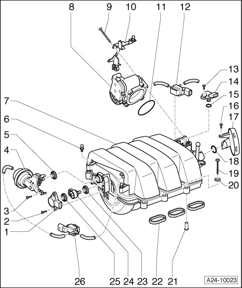
1 - Intake Manifold Tuning (IMT) Valve Position Sensor -G513-
8 - Throttle Valve Control Module -J338-
Integrated with the following:
• Throttle Drive (for Electronic Power Control (EPC)) -G186-
• Throttle Drive Angle Sensor 1 (for Electronic Power Control (EPC) -G187-
• Throttle Drive Angle Sensor 2 (for Electronic Power Control (EPC) -G188-
12 - Intake Manifold Runner Control (IMRC) Valve -N316-
14 - Intake Air Temperature (IAT) Sensor -G42- and Manifold Absolute Pressure (MAP) Sensor -G71-
26 - Intake Manifold Flap Change-over Valve -N239-
Evaporative Emission (EVAP) Canister
Purge Regulator Valve
3 - Evaporative Emission (EVAP) Canister Purge Regulator Valve 1 -N80- connector
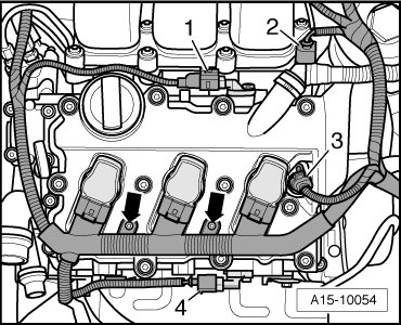
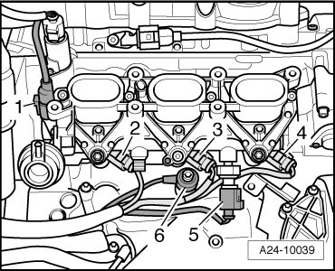
Intake Manifold Cylinder Bank 1
(Right)
1 - Intake Manifold Runner Position Sensor -G336-
2 - Cylinder 1 Fuel Injector -N30-
3 - Knock Sensor 1 -G61-
4 - Cylinder 2 Fuel Injector -N31-
5 - Cylinder 3 Fuel Injector -N32-
Component Location Front on Engine
1 - Engine Coolant Temperature (ECT) Sensor -G62-
2 - Intake Manifold Flap Change-over Valve -N239-
3 - Intake Manifold Tuning (IMT) Valve Position Sensor -G513-
Intake Manifold Cylinder Bank 2
(Left)
1 - Intake Manifold Runner Position Sensor 2 -G512-
2 - Cylinder 6 Fuel Injector -N84-
3 - Cylinder 5 Fuel Injector -N83-
4 - Cylinder 4 Fuel Injector -N33-
5 - Fuel Pressure Sensor -G247-
6 - Knock Sensor 2 -G66-
Engine Speed (RPM) Sensor
Arrow - Engine Speed (RPM) Sensor -G28-
Brake Light Switch/Brake Pedal
Switch and Clutch Pedal Switch
1 - Brake Light Switch -F- and Brake Pedal Switch -F47-
2 - Clutch Pedal Switch -F36-
Clutch Pedal Starter Interlock
Switch

2 - Clutch Pedal Starter Interlock Switch -F194-
SIMOS Control Module

- - SIMOS Control Module -J361-
High Pressure Pump
2 - Fuel Metering Valve -N290-
Oil Pressure Switch
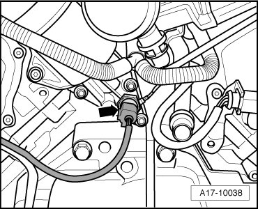
Arrow - Oil Pressure Switch -F1-
Oil Pan Lower Section
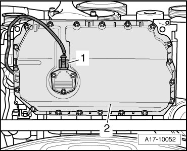
1 - Oil Level Thermal Sensor -G266- connector
EVAP Canister/Leak Detection System
Overview

11 - Leak Detection Pump (LDP) -V144-
18 - EVAP canister
Engine Control Module

- - Engine Control Module (ECM) -J623-
- Located under the E-box in the plenum chamber cover