With Generic Scan Tool
Leak Detection Pump (LDP) -V144-, Checking
Recommended special tools and equipment
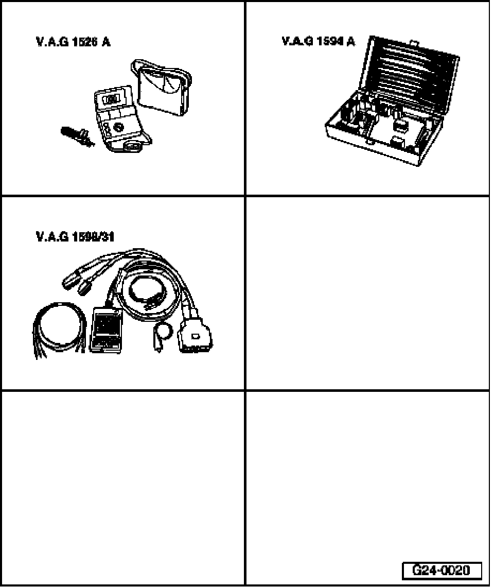
- VAG1526A hand multimeter
- VAG1594A connector test kit
- VAG1598/31 test box
Test requirements:
- Fuse for Leak Detection Pump (LDP) -V144- OK
- Fuel Pump (FP) relay OK, checking. Testing and Inspection
- Ignition switched off.
NOTE: Voltage is supplied to Leak detection pump (LDP) -V144- via the Fuel Pump (FP) relay.
Work procedure
- Remove left rear wheel.
- Remove rear left wheelhouse liner.
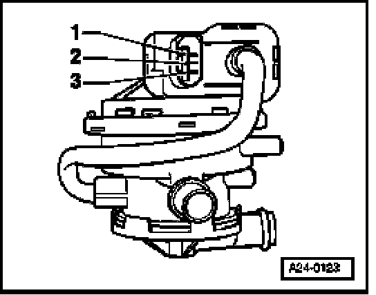
- Release and disconnect harness connector -3-.
Checking internal resistance
- Connect multimeter for resistance measurement as follows.
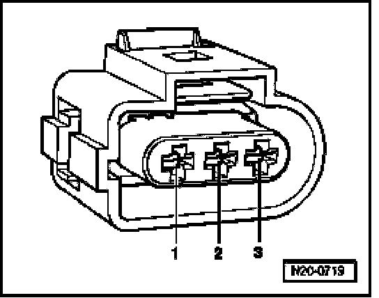
Leak Detection Pump (LDP) -V144- Terminal Specified value
1 + 3 640 ... 720 Ohms
2 + 3 15 ... 17 Ohms
If specified values are not obtained:
- Replace Leak Detection Pump (LDP) -V144- item 11.
If specified values are obtained:
Checking voltage supply
- Connect multimeter for voltage measurement as follows:
Harness connector Terminal Measure to
3 Engine Ground (GND)
- Operate starter briefly.
- Specified value: approx. battery voltage
- Switch ignition off.
If specified value is not obtained:
- Check wire connection from harness connector terminal 3 to Fuel Pump (FP) Relay -J17- via fuse for open circuit according to wiring diagram.
- Specified value: Wire resistance max 1.5 Ohm
- If necessary, repair wire connection.
If voltage supply is OK:
Checking wire connections
- Connect test box to wiring harness of Engine Control Module (ECM); ECM is not connected.

- Check the following wire connections for open circuit according to wiring diagram:
Harness connector Terminal Test box Socket
1 80
2 25
- Specified value: Wire resistance max 1.5 Ohm
- Also check wires for short circuit to each other as well as to B+ and Ground (GND).
- Specified value: Infinite Ohm (no continuity)
- If necessary, repair wire connection.
If no malfunctions are found in wires:
- Replace Engine Control Module (ECM).
Final procedures
After repair work, the following work steps must be performed in the mentioned sequence:
1 - Check DTC memory, see "Mode 3: Check DTC memory". Diagnostic Mode 3: Check DTC Memory
2 - If necessary, erase DTC memory, see "Mode 4: Reset/erase diagnostic data". Diagnostic Mode 4: Reset/Erase Diagnostic Data
3 - Generate readiness code. Readiness Code, Generating
- End diagnosis and switch ignition off.