With Generic Scan Tool
Oxygen Sensors And Oxygen Sensor Regulation Behind Catalytic Converter, Checking
NOTE: The oxygen sensor before catalytic converter (bank 1, sensor 1) regulates to Lambda 1. If this oxygen sensor is damaged, e.g. due to soiling or overheating, the regulation value may have shifted. Deviations from Lambda 1 are detected by the oxygen sensor behind catalytic converter (bank 1, sensor 2). If it recognizes the deviations downward or upward, it influences the regulation before catalytic converter, generally increasing or decreasing it respectively.
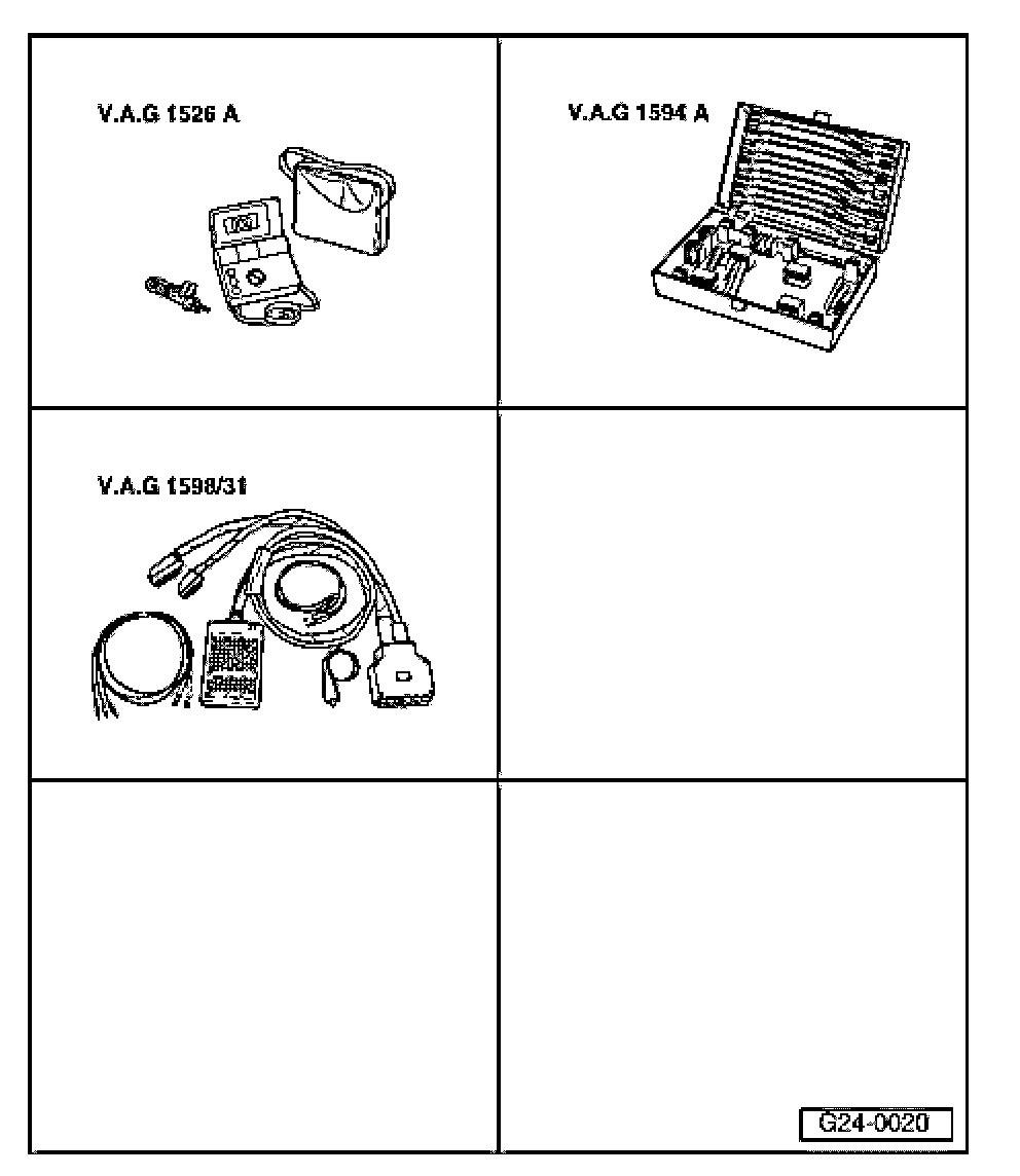
Recommended special tools and equipment
- V.A.G1526A hand multimeter
- V.A.G1594A connector test kit
- V.A.G1598/31 test box
Test requirements:
- Fuses for engine electronics OK
- Ground (GND) connections at engine and transmission OK
- Oxygen sensor heater OK; check
- Exhaust system free of leaks.
- Parking brake engaged.
- Vehicles with automatic transmission: Selector lever in position "P" or "N".
- Electrical consumers switched off (radiator fan must NOT run during test).
- A/C switched off.
- Coolant temperature at least 80 degrees C see "Mode 1: Check measuring values "; "PID 05: Coolant temperature",
Procedure
- Connect diagnostic tester.
- Start engine and let run at idle.
- In diagnostic function "33 - OBD", select "Mode 5: Check output of oxygen sensor signals".
NOTE:
- When selecting the diagnostic mode, the entry is always performed in "Bank 1 sensor 1".
- If either the V.A.G 1551/1552 Scan Tool (ST) or the VAS5051/5052 Vehicle Diagnostic, Testing and Information System is used for checking the output of oxygen sensor signals, the respective oxygen sensor can be selected by pressing buttons 1 and 2:
- Button 1 = Bank 1 sensor 1,
- Button 1 = Bank 1 sensor 1,
- Select the desired output of oxygen sensor signals according to the following table.
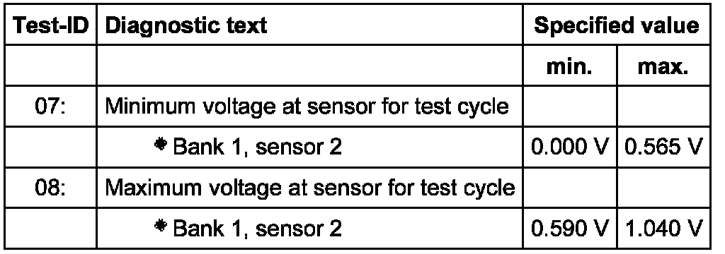

- Check values of output for oxygen sensor signals.
- *)V = Voltage in Volts (oxygen sensor signal)
- **)t = Time in seconds
If specified values are not obtained:
- Road test vehicle in order to free oxygen sensors of possible residue and repeat test.
If specified values are not obtained again:
Checking primary voltage
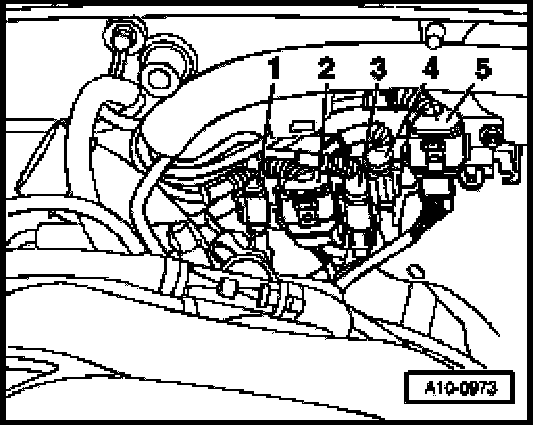
- Disconnect electrical 4-pin harness connector -2- from Oxygen Sensor (O2S) Behind Three Way Catalytic Converter TWC) -G130- (bank 1, sensor 2).
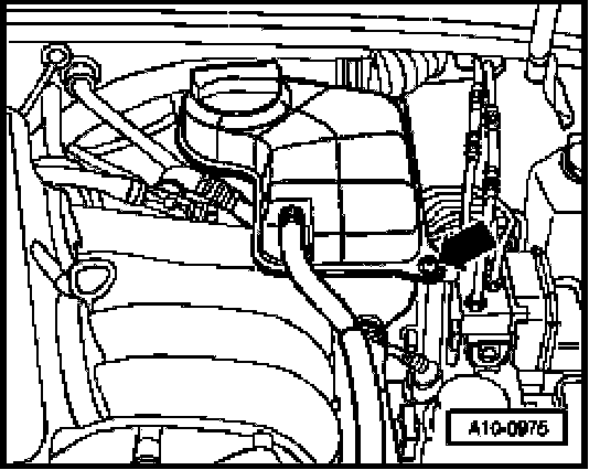
NOTE: Coolant reservoir screw (arrow) must be removed and coolant reservoir must be placed to the side in order to access harness connector. The coolant hoses remain connected.
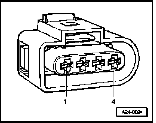
- Connect multimeter between terminal 3 and 4 for voltage measurement.
- Switch ignition on.
Specified value: 0.400 to 0.500 V
- Switch ignition off.
If specified value is not obtained:
- Test oxygen sensor wires
If specified value is obtained:
- Replace oxygen sensor behind catalytic converter
Check oxygen sensor wires for Oxygen Sensor (O2S) Behind Three Way Catalytic Converter (TWC) -G130- (bank 1, sensor 2)
- Connect test box to wiring harness of Engine Control Module (ECM). ECM is not connected.

- Check the following wire connections for open circuit according to wiring diagram.
Harness connector Terminal Test box Socket
3 68
4 69
Specified value: Wire resistance max 1.5 Ohms
- Check wires for short circuit to each other as well as to B+ and Ground (GND).
Specified value: Infinite Ohms (no continuity)
- If necessary, repair wire connection.
If no malfunctions are found in wires:
- Replace Engine Control Module (ECM).
Final procedures
After repair work, the following work steps must be performed in the mentioned sequence:
1. Check DTC memory.
2. necessary, erase DTC memory see "Mode 4: Reset/erase diagnostic data".
3. Generate readiness code. Readiness Code, Generating