With Manufacturer's Scan Tool
Secondary air system, checking
The secondary air system is designed to enable the catalytic converter to heat up and reach its operating temperature more quickly after a cold start.
Principle of operation
Due to extra mixture enrichment during cold-start phase, an increased amount of unburnt hydrocarbons is present in exhaust gas. The secondary air system improves the oxidation process in the catalytic converter, thereby reducing toxic emissions. The heat generated by oxidation accelerates the "light off" of the catalytic converter and significantly improves exhaust gas quality during warm-up.
Function
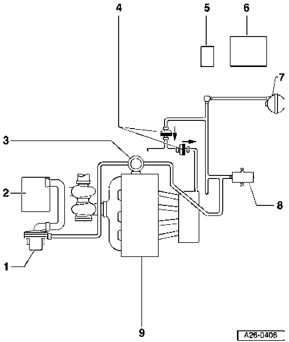
^ After cold start, engine control module -6 activates secondary air pump -1- via Secondary Air Injection (AIR) pump relay -5-, and air is fed to secondary air combination valve -3-.
^ At the same time the system activates Secondary Air Injection (AIR) solenoid valve -8 which supplies vacuum to secondary air combination valve -3-. The relevant combination valve opens a passage for the secondary air system to supply air to exhaust ports in cylinder head.
1. Secondary Air Injection (AIR) pump motor -V1 01 - Installation location, Refer to Fig 1
2. Air cleaner
3. Secondary air combination valve
^ Installation location, Refer to Fig 3
4. Non-return valve
^ Installation position (light/dark side and direction of arrow): As shown in illustration. Arrow indicates direction of flow.
5. Secondary Air Injection (AIR) pump relay -J299
^ Installation location, Refer to Fig 3
6. Engine control module -J220
7. Vacuum reservoir
^ Installation location: in front left wheel housing behind wheel housing liner
8. Secondary Air Injection (AIR) solenoid valve -N1 12
^ Installation location, Refer to Fig 1
9. Cylinder head

Fig. 1 Installation location of Secondary Air Injection (AIR) solenoid valve -N112
^ Installation location: under intake manifold
1-Recirculation valve for turbocharger -N249- (green connector)
2-Secondary Air Injection (AIR) solenoid valve -N112 (brown connector)
Note: Illustration shows removed intake manifold viewed from below.
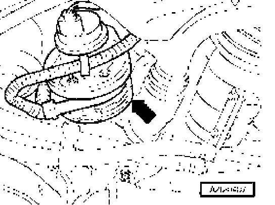
Fig. 2 Installation location of Secondary Air Injection (AIR) pump motor -V1 0-1
^ Front right in engine compartment below air cleaner housing
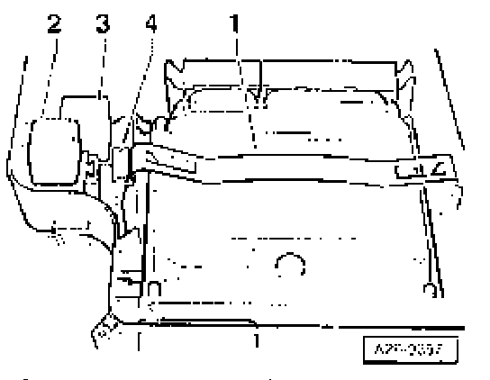
Fig. 3 Installation location of Secondary Air Injection (AIR) pump relay -J299
^ 3-way relay carrier in electronics box in plenum chamber, plug-in position 2
1-Engine control module
2-Secondary Air Injection (AIR) pump relay -J299
3-Motronic Power Supply relay -J271
4-Fuse -S130 for secondary air pump

Fig. 4 Secondary air combination valve
^ Rear right on cylinder head