Diagram 57/1
Comfort system, Outside Mirror, heated and adjustable, Door opener lighting, Alarm system, Entry lights, Power Window, Front Interior Lights, Luggage Compartment Light, Door warning lights, Central Locking System, from 2004 m. y.
IMPORTANT NOTE:
This manufacturer uses "Track" style wiring diagrams.
For information on how to use these diagrams effectively, please refer to Diagram Information and Instructions. Diagram Information and Instructions
Main fuse
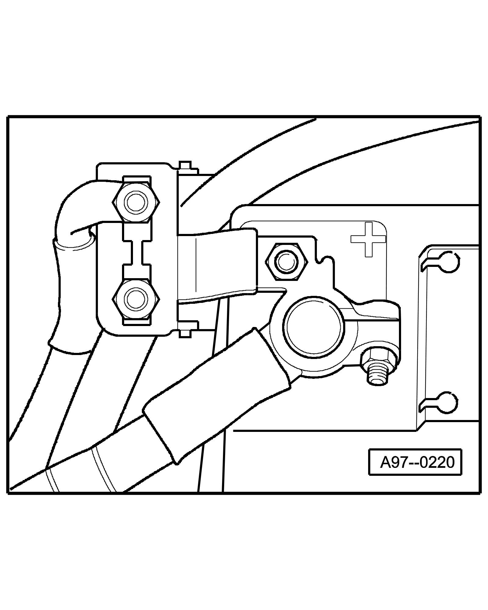
• on the Battery
Fuse holder
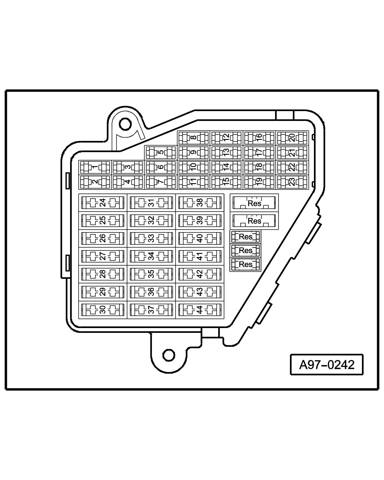
• Instrument panel driver side
Fuse Colors
30 A - Green
25 A - Withe
20 A - Yellow
15 A - Blue
10 A - Red
7,5 A - Brown
5 A - Beige
Note::
• Fuse in fusebox from 23 onwards are numbered 223 onwards in Current Flow Diagram.
Coupling station with threaded connection

• in the electronics box, plenum chamber
3 - 17-Pin Connector, red (T17d)
Connector station A-pillar

• behind side trim, left
9 - 17-Pin Connector, dark brown (T17g)
10 - 17-Pin Connector, orange (T17f)
14 - 10-Pin Connector, grey (T10d)
15 - 17-Pin Connector, green (T17b)
4-Pin Relay Carrier with threaded connection

• Instrument panel driver side
9-Pin Relay Carrier with Vehicle Electrical System Control Module

• Instrument panel driver side, behind 3-Pin Relay Carrier
D - Power Window Fuse 2 (S280)
F - Power Window Fuse (S37)
Next Diagram 57/2 (Tracks 1-14)