With Generic Scan Tool
Check Knock Sensors
Recommended special tools and equipment
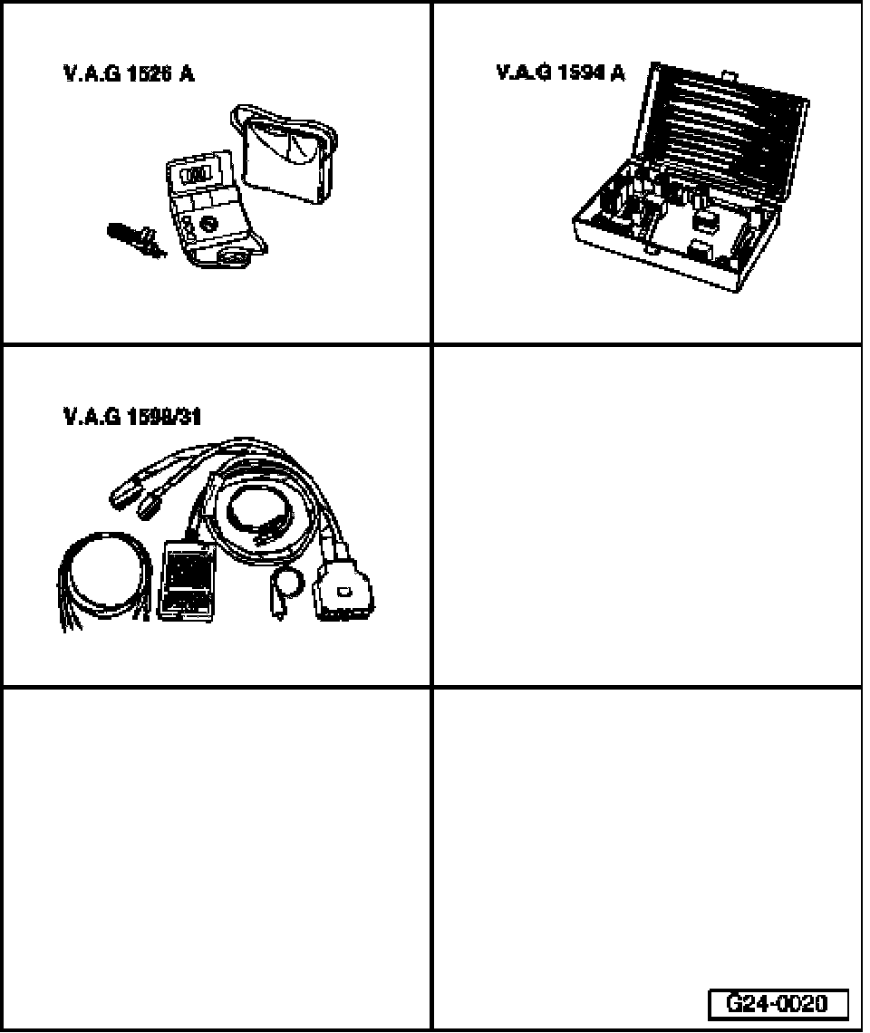
- VAG1526A multimeter
- VAG1594A connector test kit
- VAG1598/31 test box
NOTE:
- Knock Sensor (KS) 1 -G61- and Knock Sensor (KS) 2 -G66- themselves cannot be electrically tested.
- When servicing terminals in harness connector of knock sensors, use only gold-plated terminals.
- For the Knock Sensors to function properly, it is important for tightening torque to be exactly 20 Nm.
- Check harness connector from knock sensor to wiring harness for corrosion.
Test requirement:
- Ignition switched off.
Checking knock sensor wiring
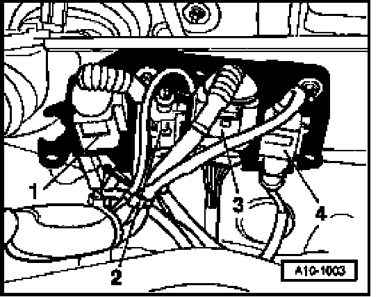
- Disconnect electrical 3-pin harness connector -2- for Knock Sensor (KS) 1 -G61-.
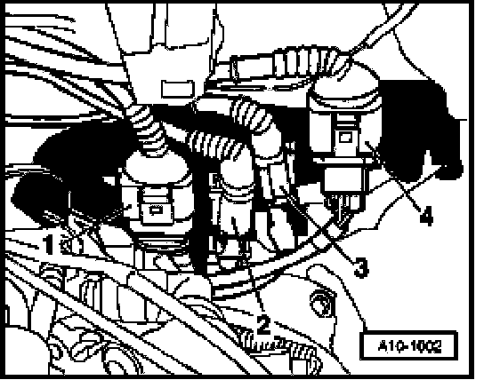
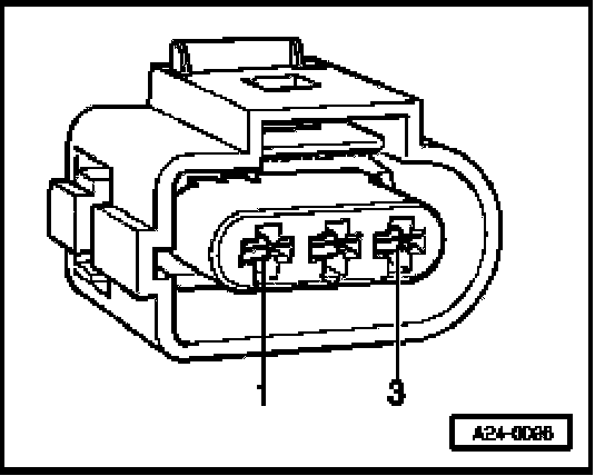
- Disconnect electrical 3-pin harness connector -3- for Knock Sensor (KS) 2 -G66-.
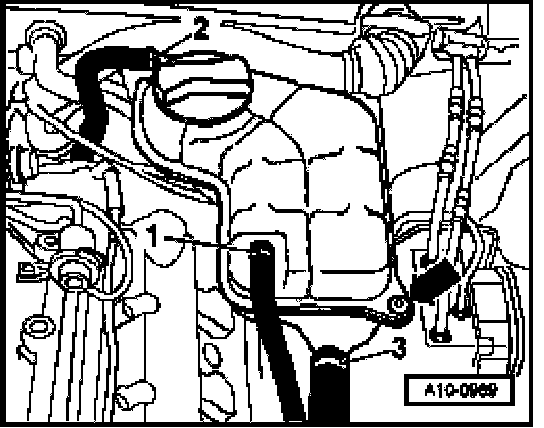
NOTE: To reach the harness connectors, the left cover in engine compartment must be removed, the line to Engine Coolant Level (ECL) Warning Switch at bottom on reservoir must be disconnected, and the bolt -arrow- of the coolant reservoir must be unscrewed and set aside. Coolant hoses -1- to - 3- remain connected.
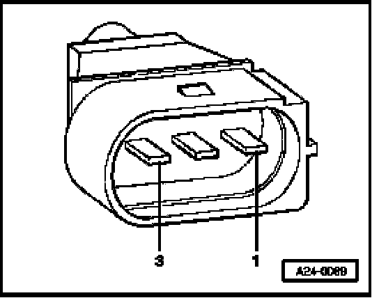
- Check all three terminals at knock sensor connector for short circuit to each other (terminal 1+2, 1+3, 2+3).
- Specified value: infinity Ohm (no continuity) - the wires must not have any connection to each other
- If there is a connection , replace knock sensor.
If no malfunction can be found:
Check wires from knock sensors to Engine Control Module (ECM)
- Connect test box to wiring harness of Engine Control Module (ECM); ECM is not connected. Text Box, Connecting For Wiring Test
- Check the following wire connections for open circuit according to wiring diagram:
- Knock Sensor (KS) 1 -G61- (bank 1)
Harness connector Test box
Terminal Socket
1 (signal) 106
2 (Ground -GND-) 99
3 (shielding) 108
- Knock Sensor (KS) 2 -G66- (bank 2)
Harness connector Test box
Terminal Socket
1 (signal) 107
2 (Ground -GND-) 99
3 (shielding) 108
- Specified value: Wire resistance max 1.5 Ohm
- Also check wires for short circuit to each other as well as to B+ and Ground (GND).
- Specified value: infinity Ohm (no continuity)
- If necessary, repair wire connection.
Final procedures
After repair work, the following work steps must be performed in the mentioned sequence:
1 - Check DTC memory, Diagnostic mode 3 - Check DTC memory. Diagnostic Mode 3: Check DTC Memory
2 - Erase DTC memory, diagnostic mode 4 - Reset/erase diagnostic data. Diagnostic Mode 4: Check Reset/Erase Diagnostic Data
3 - Generate readiness code. Readiness Code, Generating
- End diagnosis and switch ignition off.