Electrical Testing
Electrical Testing
NOTE:
- Connect VAG 1598A test box to vehicle wiring harness. Scan Tool Connecting and Initial Checks
- Observe notes at electrical testing onward.
- The socked assignment on VAG 1598/11 adapter corresponds exactly to the terminal assignment on the A/C Control Head -E87-.
- A variety of information is send via the CAN-bus-Comfort, no electrical testing applies for this information (See Read measuring value block.
- The following signals are displays as input signals in measuring value block and are not covered in electrical testing (See Read measuring value block):
- Input signal for windshield wiper and windshield washer pump.
- Signal for running light and dimming of illumination of A/C Control Head -E87-.
- Signal from Sensor for air quality.
- Signal for idle speed increase and A/C compressor cut-off from engine control module.
- Activation signal for heated front window.
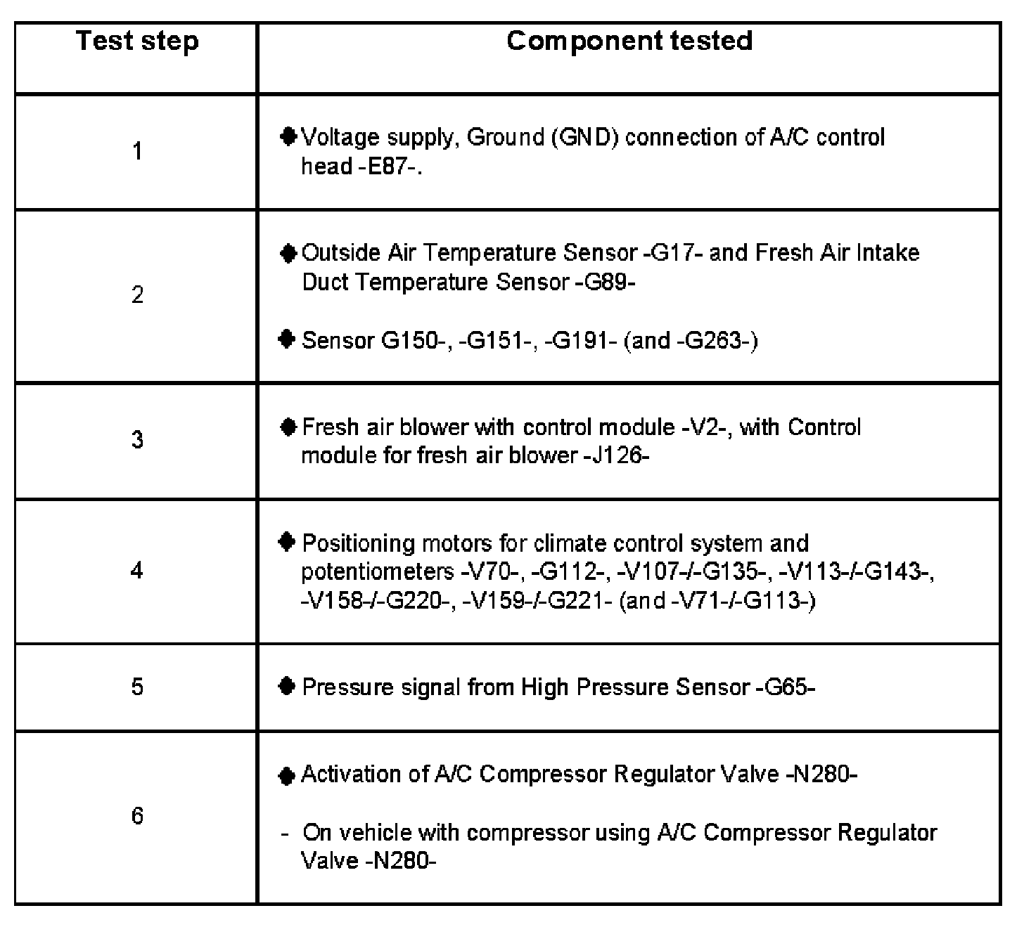
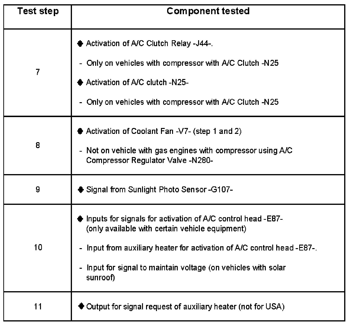
Electrical tests overview on A/C Control Head -E87-
Test Step 1 - 6:
Test Step 7 - 11:
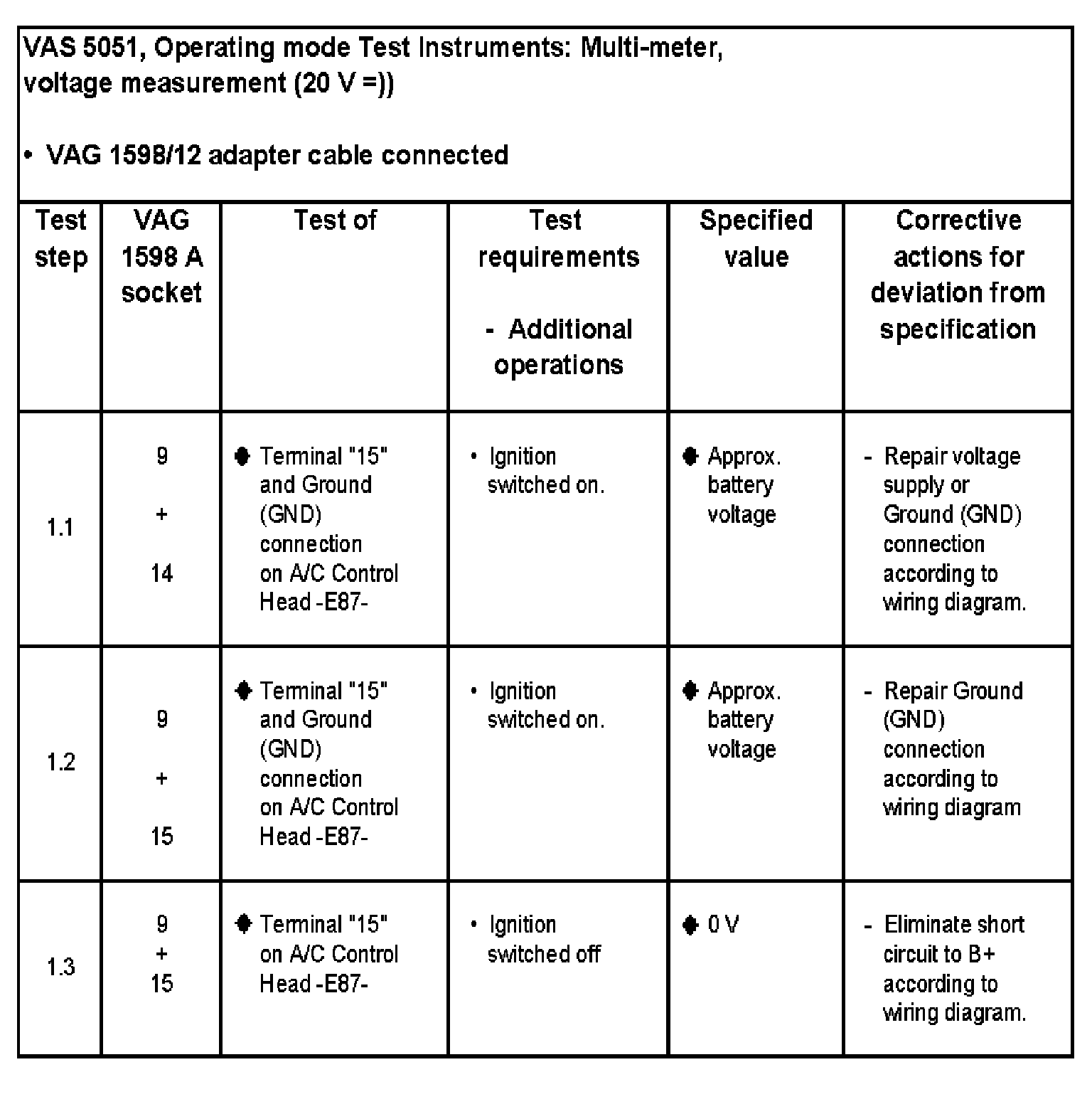
Test step 1 to 4
Test step 1: Voltage supply, Ground (GND) connection of A/C control head -E87-.
Test Step 1.1 - 1.3:
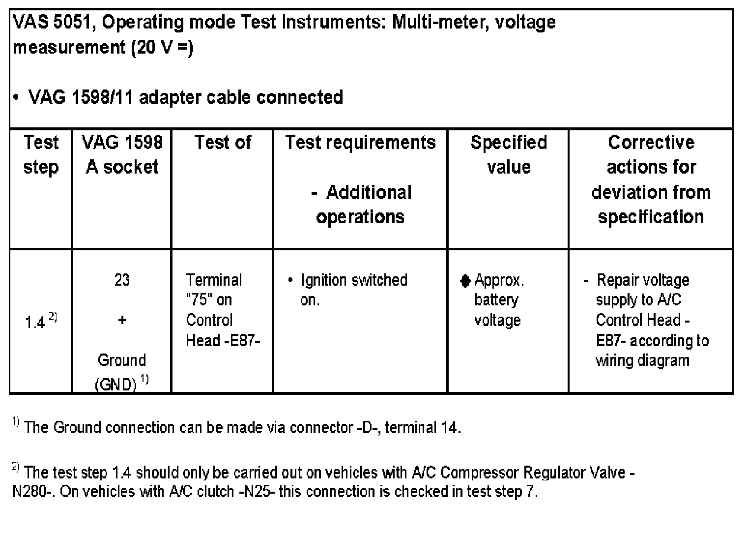
Test Step 1.4:
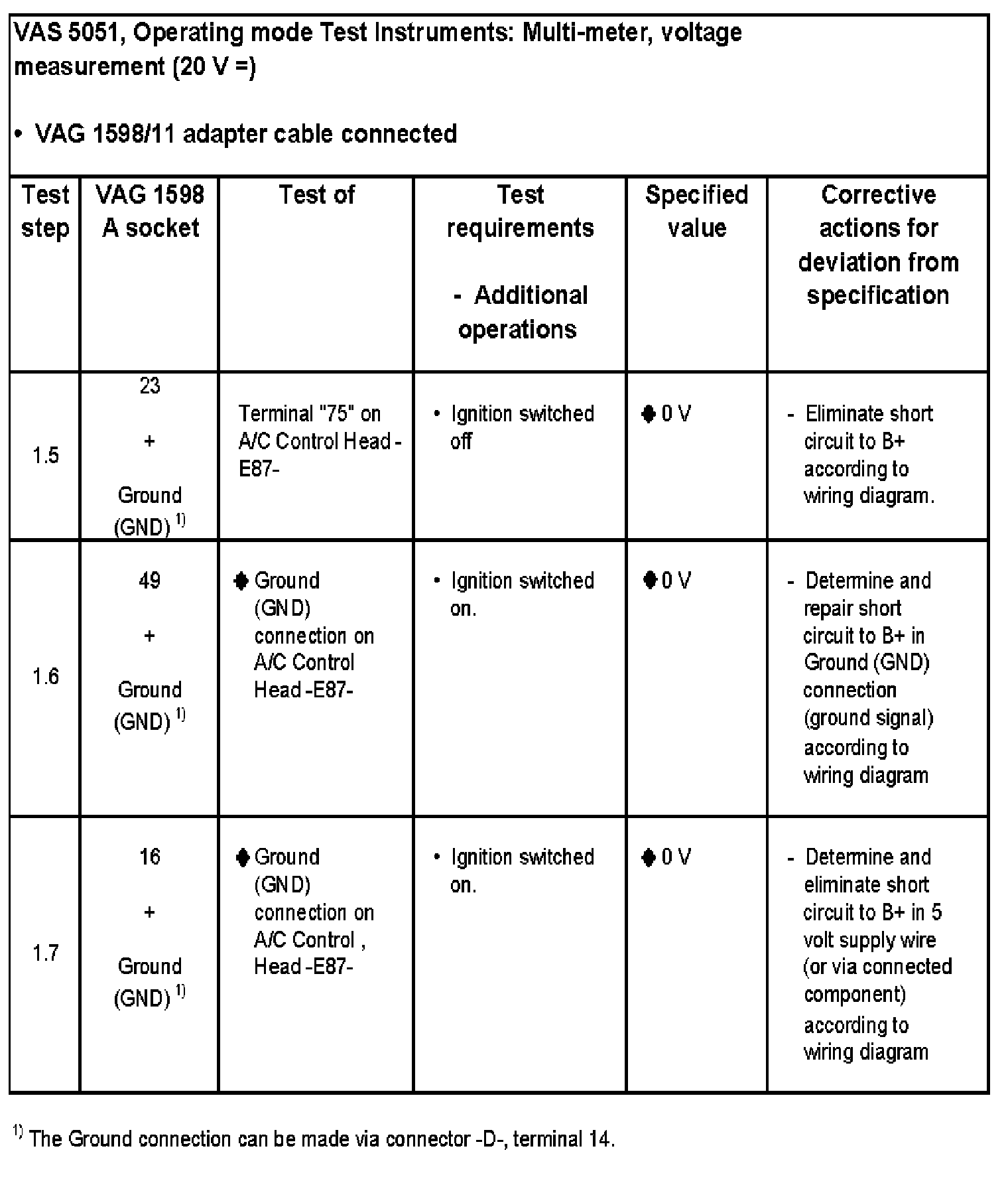
Test Step 1.5 - 1.7:
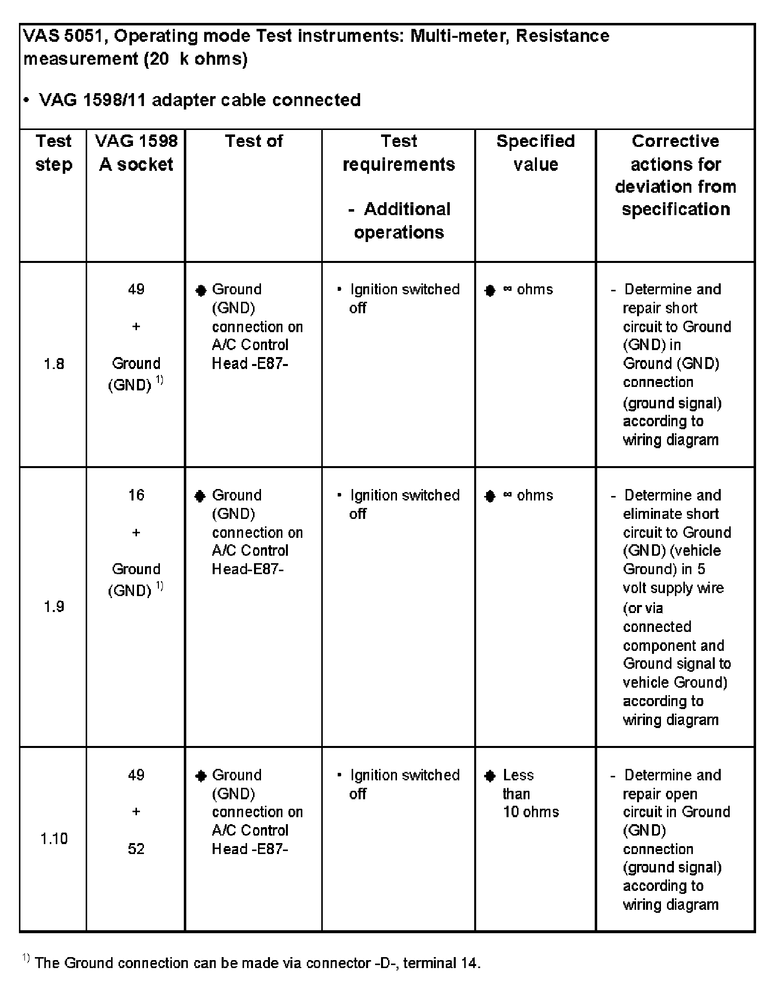
Test Step 1.8 - 1.10:
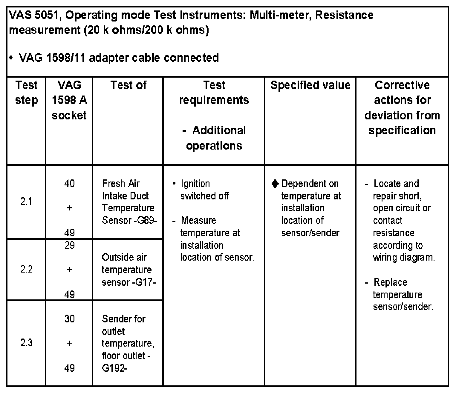
Test Step 2.1 - 2.3:
Test Step 2.4 - 2.5:

Test Step 2.6:
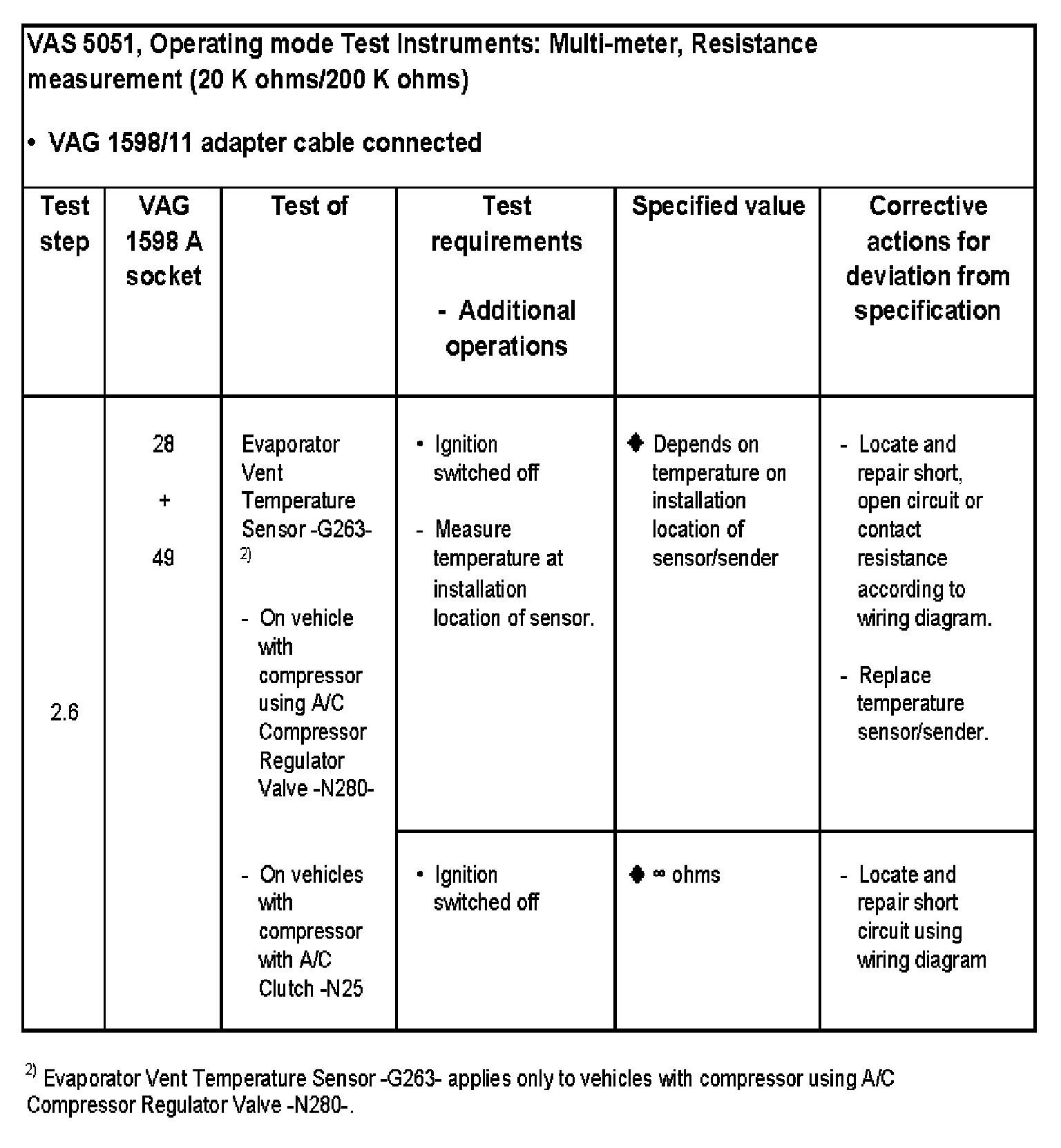
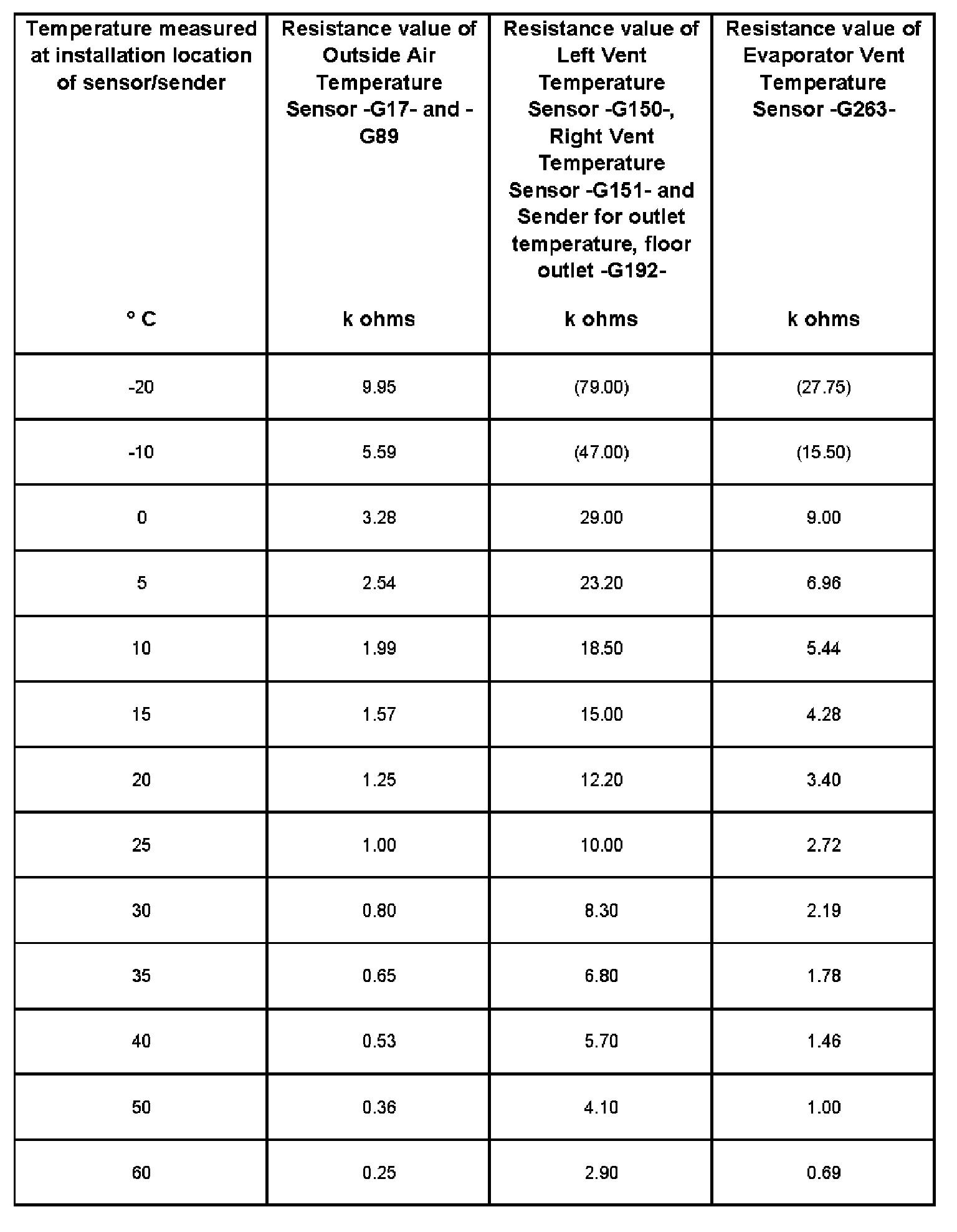
Temperature depending resistance values of sensor/sender:
Test step 3
Fresh air blower -V2- and Control module for fresh air blower -J126-
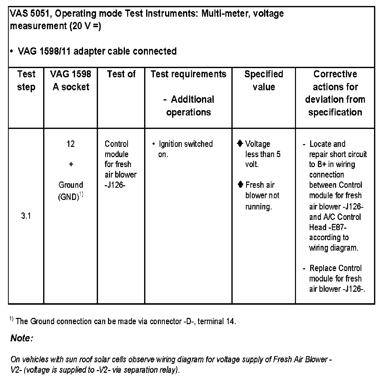
Test Step 3.1:
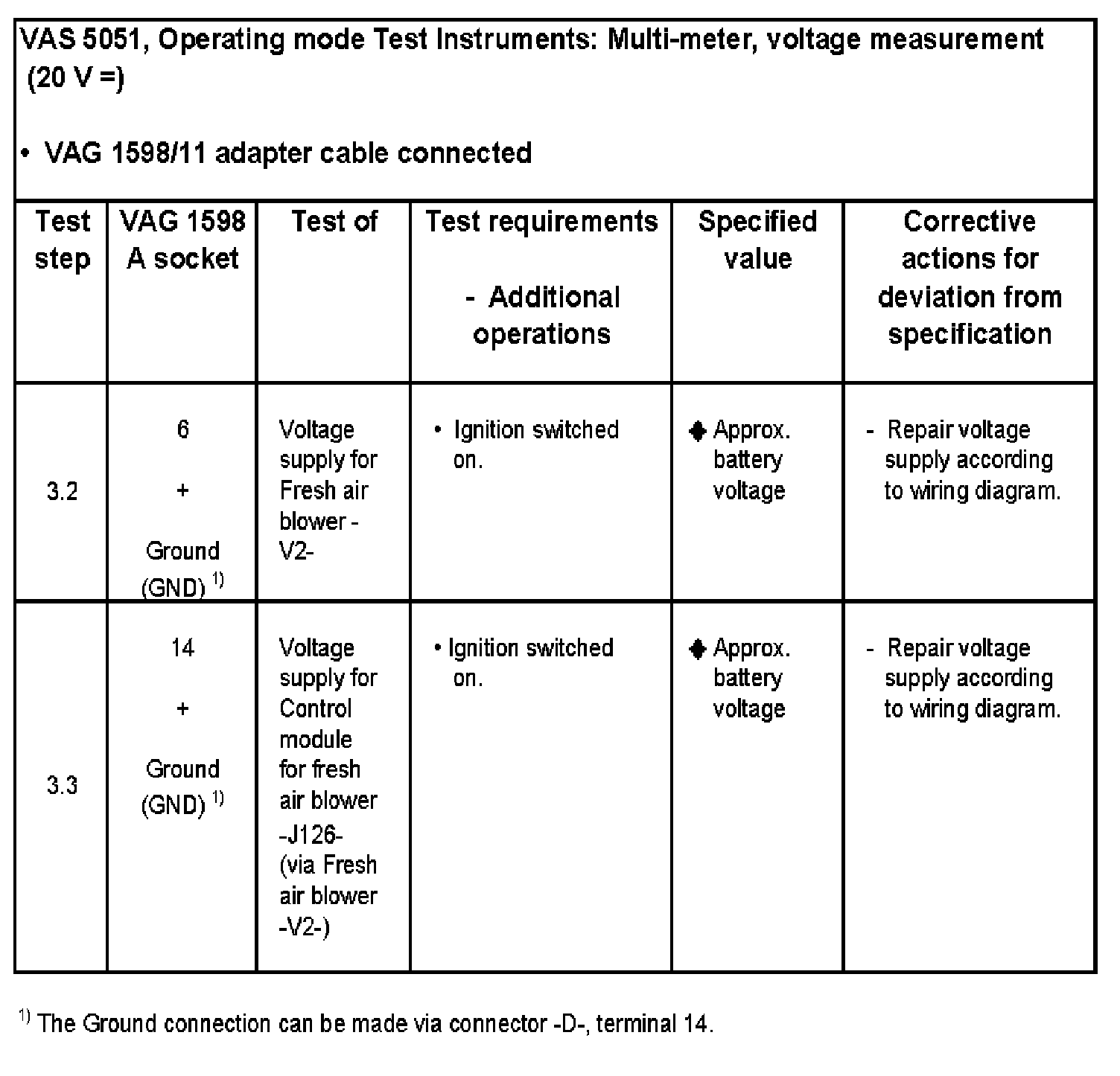
Test Step 3.2 - 3.3:
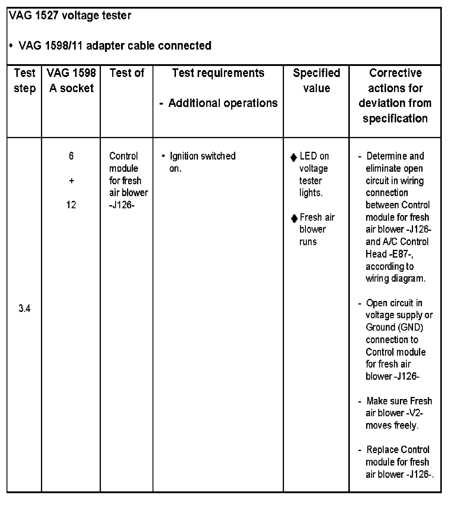
Test Step 3.4:
Test step 4:
Air conditioner positioning motors with potentiometers
NOTE:
- The resistance value of potentiometer in the positioning motors (Specification: 3,6... 5.7 kohms between terminal 1 and 3 can only be measured at the motor directly (connected in parallel).
- The resistance of the potentiometers in the positioning motors (between terminals 1 and 2 and between terminals 3 and 2) depends on the position of the positioning motor and must always be measured with the positioning motors installed. The upper specified value is not attained in test steps 4.1 and 4.2. (In order to reach the upper specified value, all harness connectors from other positioning motors must be disconnected during the measurement (switched in Parallel).
- If the A/C Control Head -E87- detects the malfunction "Potentiometer shod circuit to Ground (GND)" or "Open/short circuit to B+", check all the potentiometers and the wiring.
- If DTC memory recognizes several positioning motors as faulty and the malfunction cannot be detected in test step 4, check potentiometers in all positioning motors and the wiring connection between the positioning motors for shod circuit (e.g. with harness connectors disconnected between -V107- and -V70- and -E87- between socket 1, 2 and 3 in pertaining connector the tester must read infinity ohms
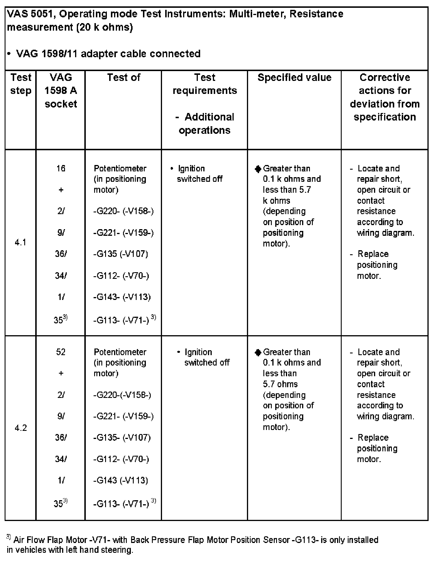
Test Step 4.1 - 4.2:
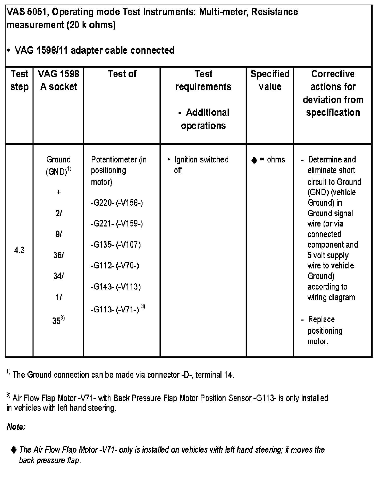
Test Step 4.3:
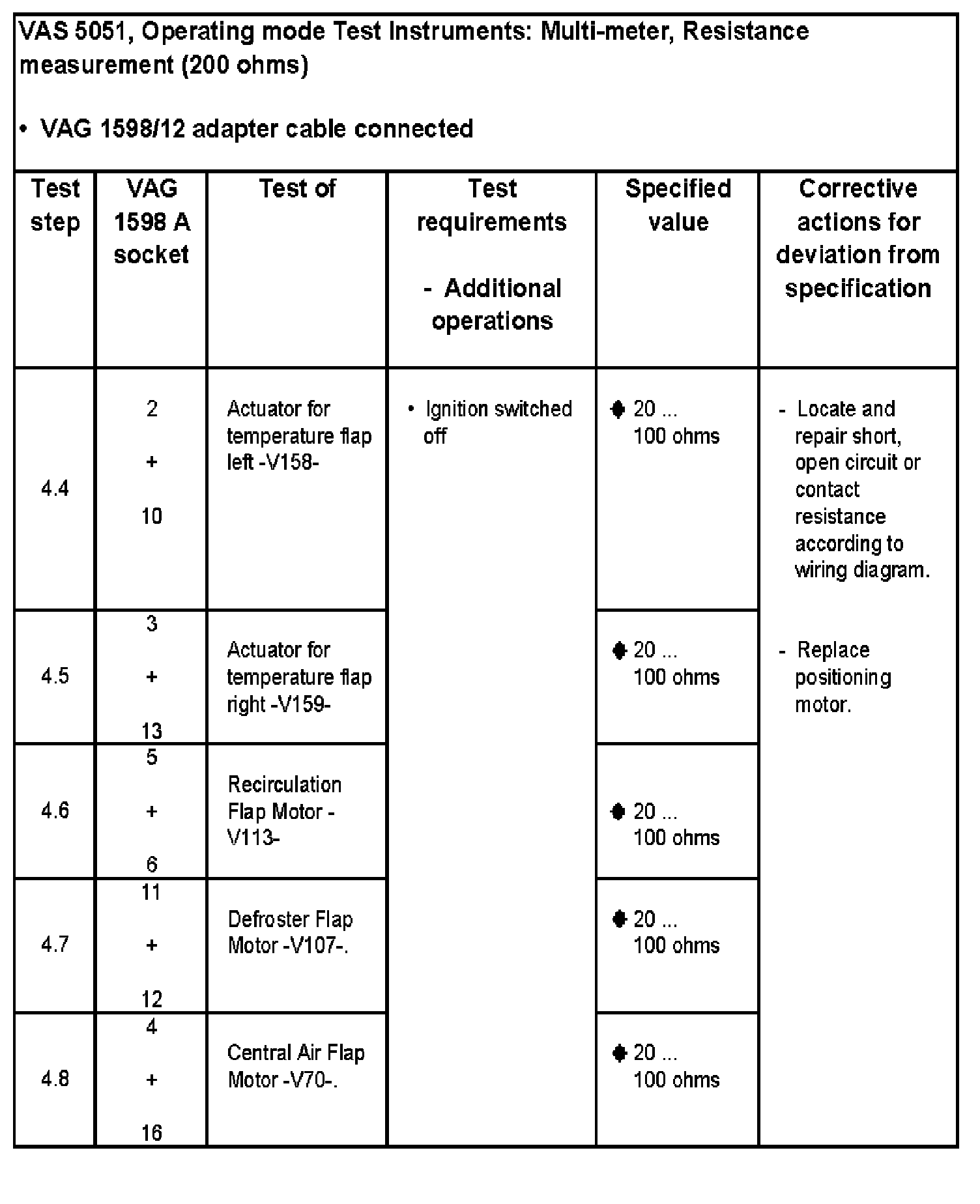
Test Step 4.4 - 4.8:
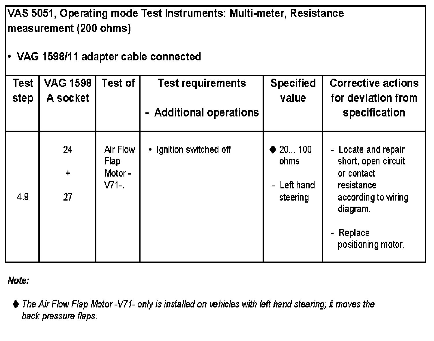
Test Step 4.9:
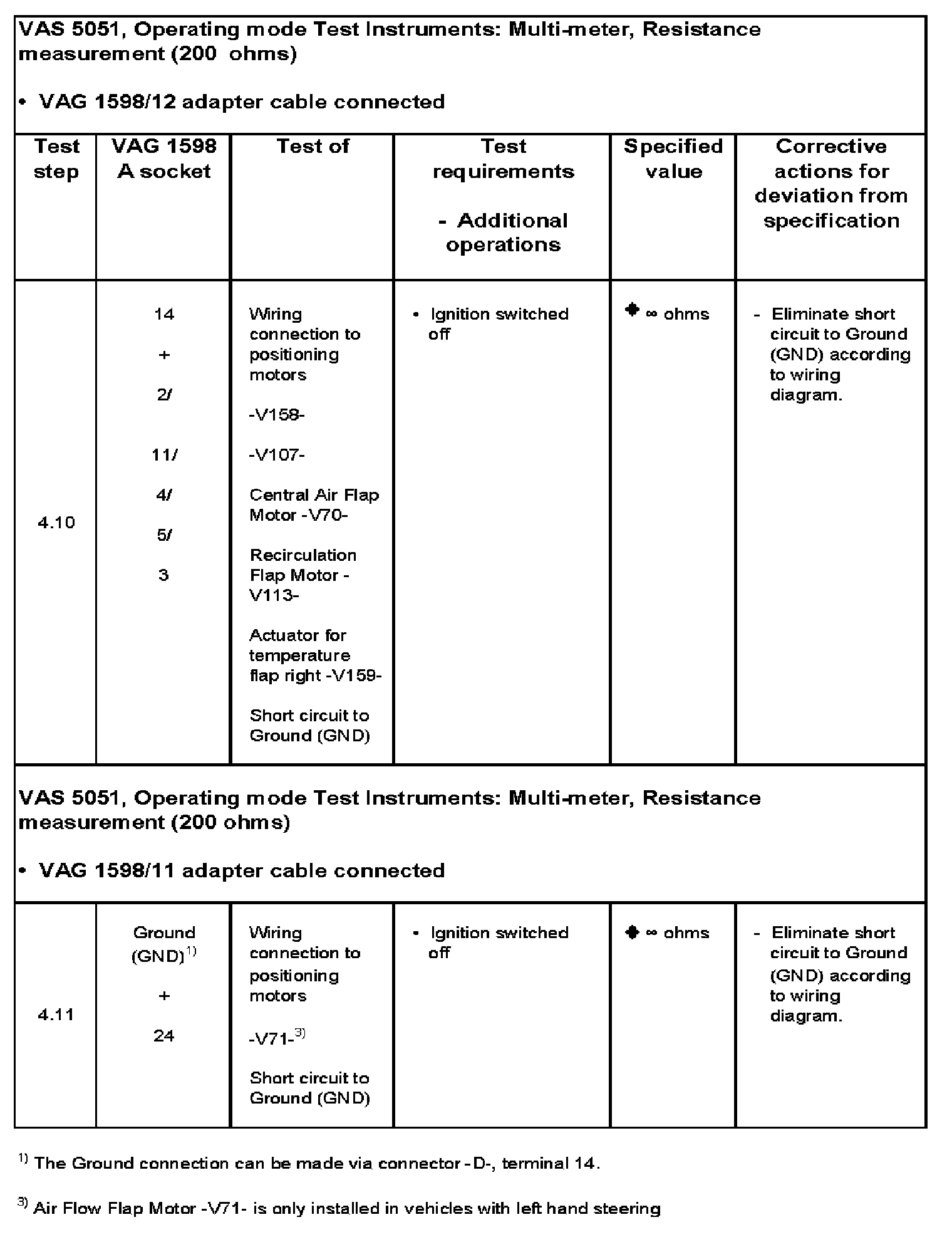
Test Step 4.10 - 4.11:
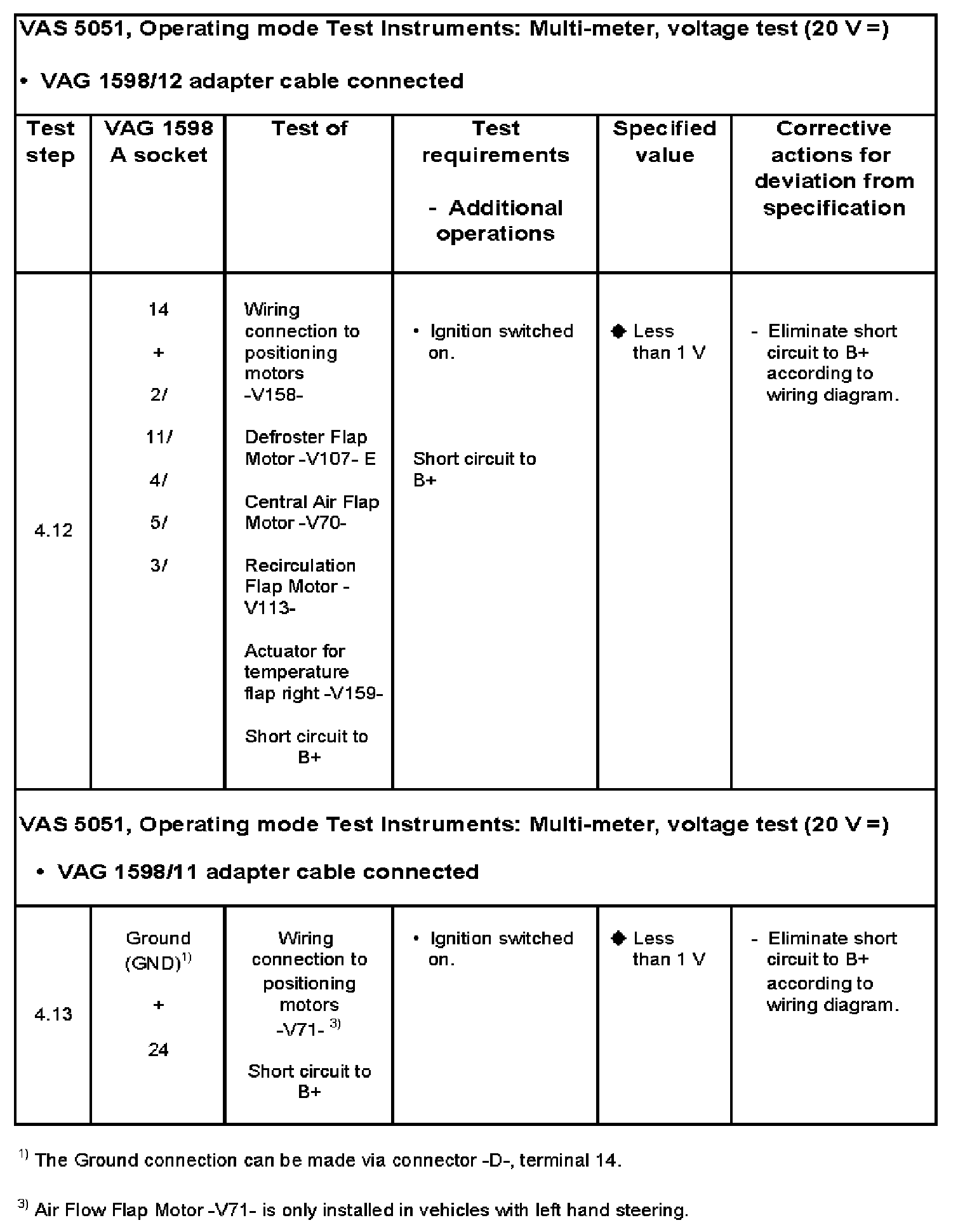
Test Step 4.12 - 4.13:
Test step 5 to 9
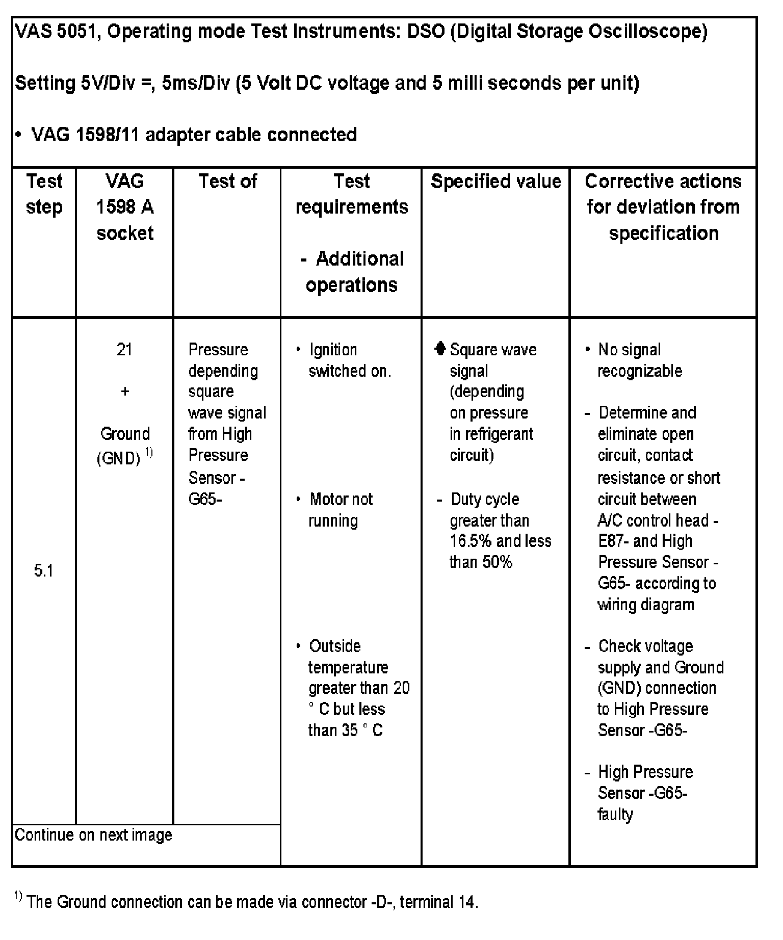
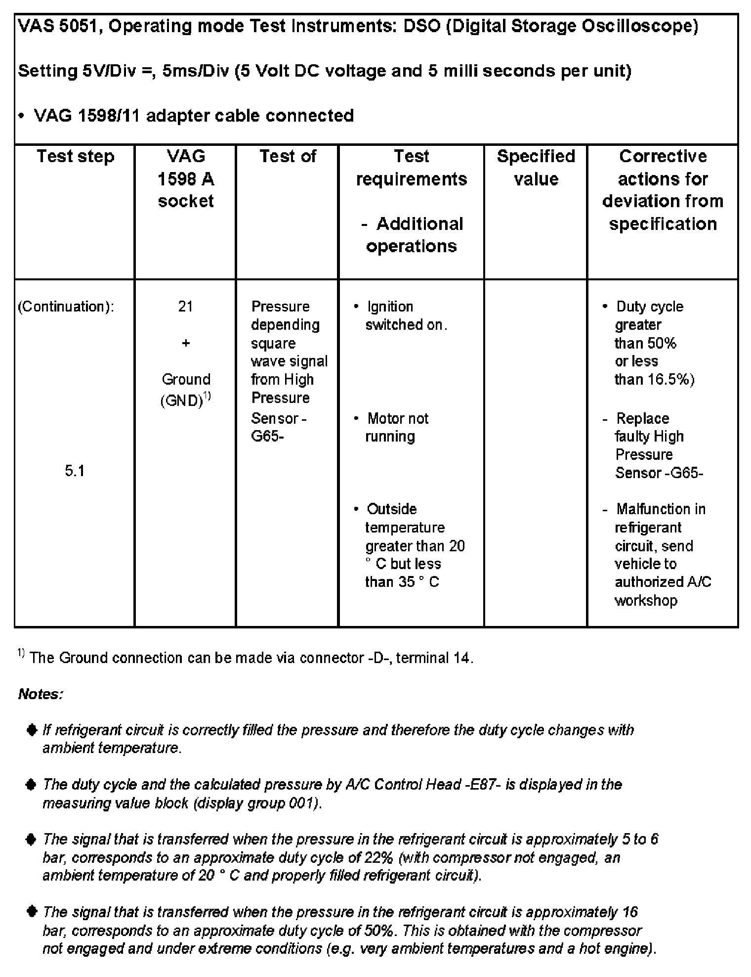
Test step 5: Pressure signal from High Pressure Sensor -G65-
Test Step 5.1, Part 1:
Test Step 5.1, Part 2:
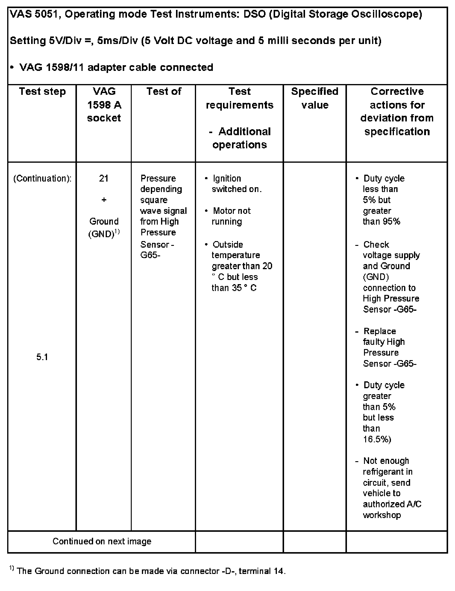
Test Step 5.1, Part 3:
Checking pressure signal from High Pressure Switch -G65-
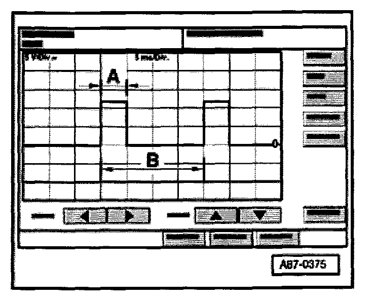
The oscilloscope shows this display when the following conditions are met.
- Ignition switched on (B+ and Ground available at High Pressure Switch -G65-)
- Setting on oscilloscope: 5 V/Div. = (5V per unit DC voltage) 5 ms/Div. (5 Milli seconds per unit)
- Measuring lead (signal lead) connected to socket -21- of VAG 1598/11 test box.
- Measuring cable (shielded) connected to terminal -14- on connector -D- of A/C Control Head -E87- or vehicle Ground (GND).
NOTE:
- The display shows a signal that is transferred when the pressure in the refrigerant circuit is approximately 7 bar, it corresponds to an approximate duty cycle of 25% (with compressor not engaged, an ambient temperature of 30 °C and properly filled refrigerant circuit)
- The impulse width -A- depends on the pressure in the refrigerant circuit (if pressure increases, area -A- is getting wider).
- The signal distance -B- is always 20 milli seconds (corresponds to frequency of 50 Hertz).
- The duty cycle is determined by the ratio of impulse width -A- and signal distance -B-.
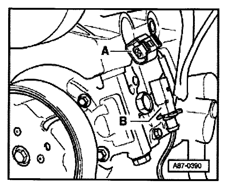
Connector assignment at High Pressure Switch -G65-
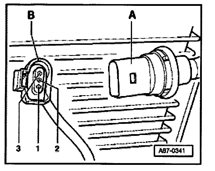
Terminal 1 Ground (GND)
Terminal 2 Signal output (square wave signal to -E87-)
Terminal 3 B+ (terminal 75)
NOTE:
- With harness connector -B- disconnected, the compressor will not engage.
- The high pressure sensor -A- is an electronic control module, which creates a square wave signal, the duty cycle ratio changes with pressure in the refrigerant circuit.
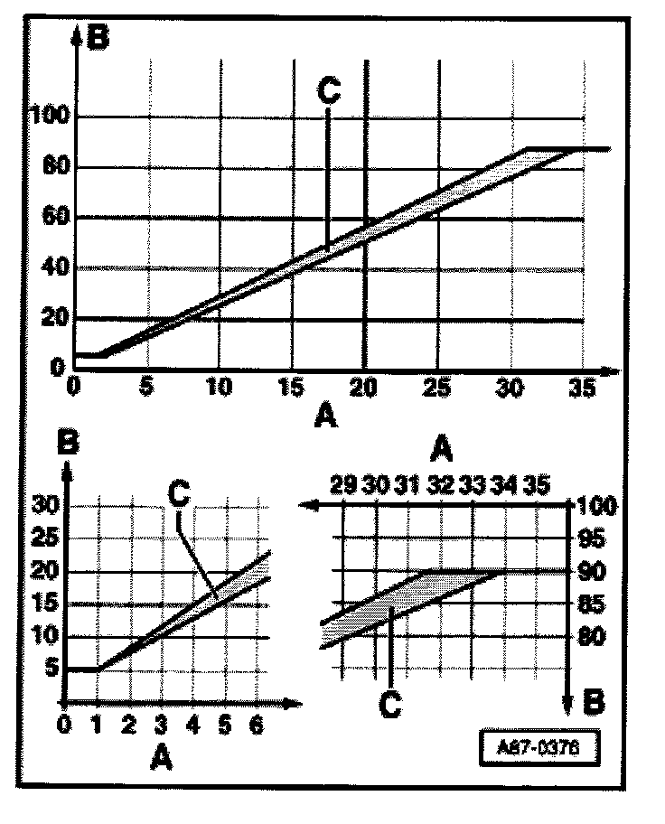
Pressure signal from High Pressure Sensor -G65-
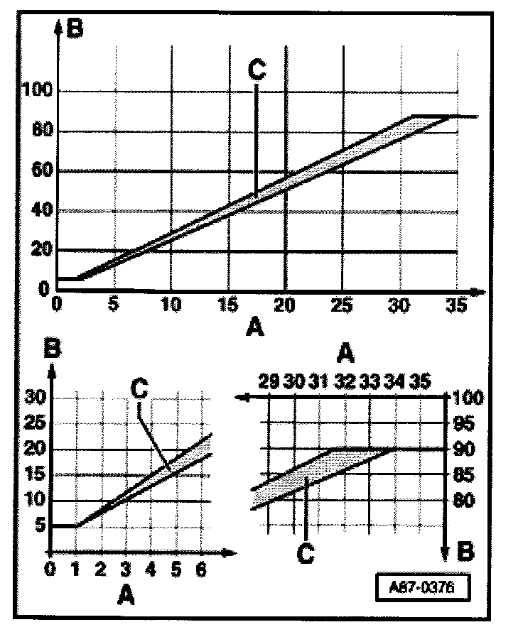
A - Refrigerant system pressure, high pressure side" in bar (absolute pressure)
B - Signal ratio of square wave signal
C - Characteristic curve
NOTE:
- The A/C control head -E87- switches the compressor on as soon as no compressor cut-off condition exists (by activating the A/C Compressor Regulator Valve -N280- or A/C Clutch Relay -J44-).
-- If the duty cycle is greater than 12% (absolute pressure corresponds approx.: 1.8 bar), if less than 87.5% (pressure corresponds to approx.: 32 bar).
-- The compressor is not switched on if the duty cycle is less than 12 % or greater than 87.5 % (A/C Compressor Regulator Valve -N280- is not activated).
- The duty cycle and the calculated pressure by A/C Control Head -E87- is displayed in the measuring value block See(display group 001).
- At absolute pressure, 0 bar corresponds to absolute vacuum. Normal ambient pressure corresponds to approximately 1 bar absolute pressure. 0 pressure corresponds to an absolute pressure of one bar on most pressure gauges (indicated by -1 below 0).
For vehicles with compressor using A/C Compressor Regulator Valve -N280- (coding of A/C control head -E87-)
- The A/C Control Head -E87- sends the request to switch on the coolant fans to the Engine Control Module (ECM) via the CAN-bus system, the ECM switches via the coolant fan control module the coolant fans on.
-- Independent from pressure in refrigerant circuit as soon as compressor is switched on.
- The A/C Control Head -E87- the request for increased coolant fan speed via the CAN-bus system to the Engine Control Module (ECM):
-- Vehicles with gas engines request 100% fan speed currently at approx.: 26 bar pressure in the refrigerant circuit.
For vehicles with A/C compressor regulator valve -N280- (coding of -E87-)
- The -E87- switches via a separate wire connection to -J26 and -J101- the coolant fan on:
-- The first speed independent from pressure in refrigerant circuit as soon as compressor is switched on.
-- The second speed is currently activated at 100 % with a pressure of 16 bar in the refrigerant circuit.
For vehicles with compressors using A/C clutch -N25- (coding of -E87-):
- The A/C Control Head -E87- switches the cooling fan on via a separate wiring connection to Coolant Fan control (FC) Relay -J26- and Second Speed Coolant Fan Control (FC) Relay -J101- or to Coolant FC (Fan Control) Control Module -J293-:
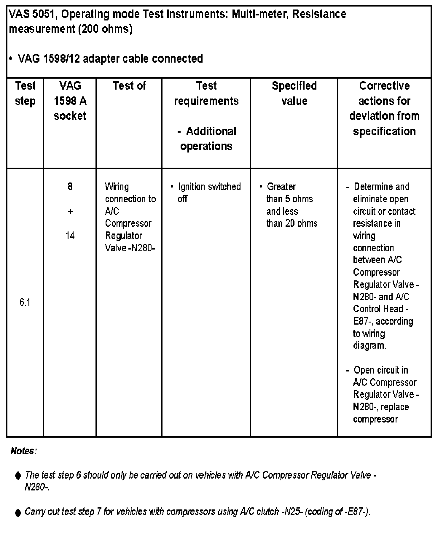
Test Step 6.1:
Test Step 6.2 - 6.3:
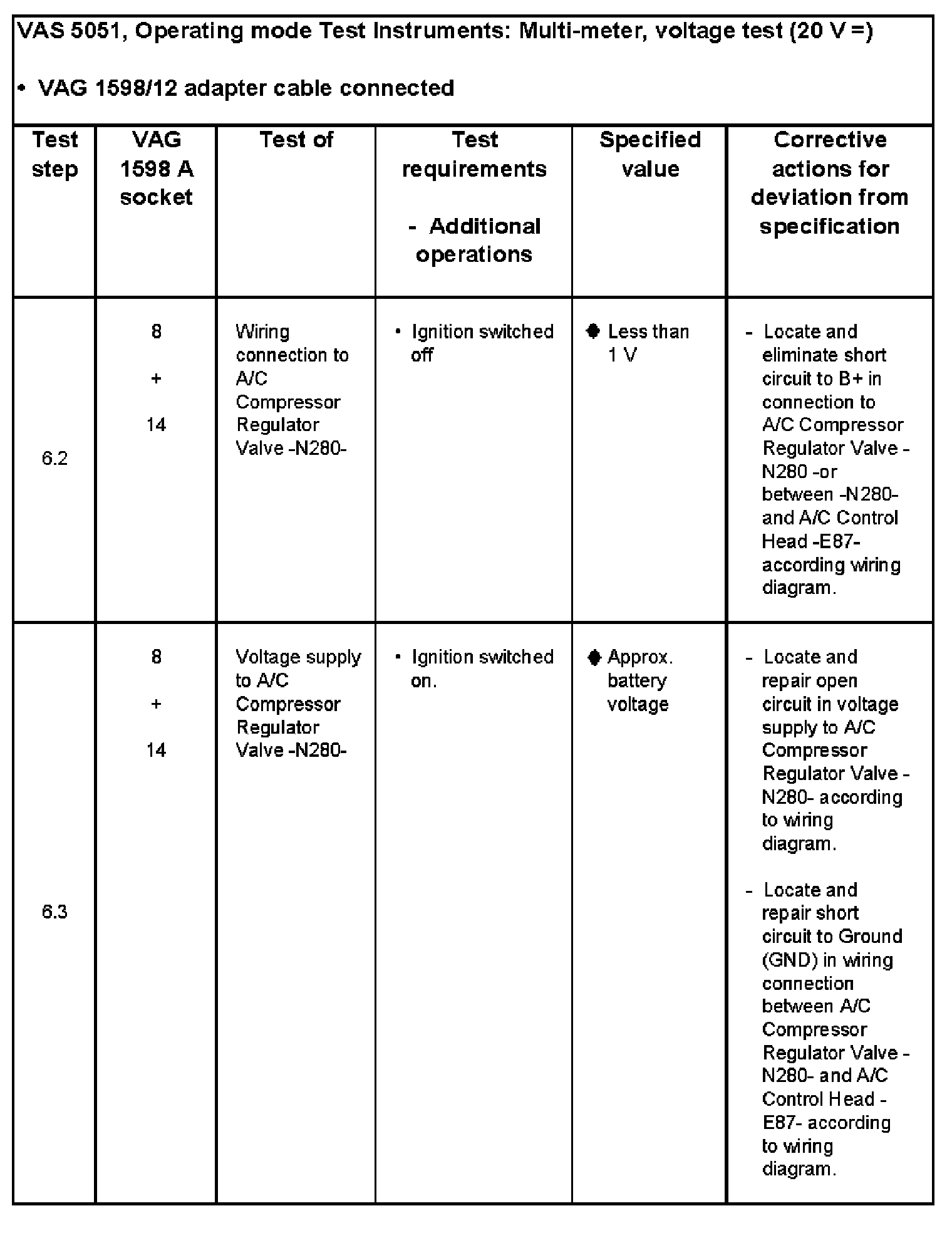
Test Step 6.4:
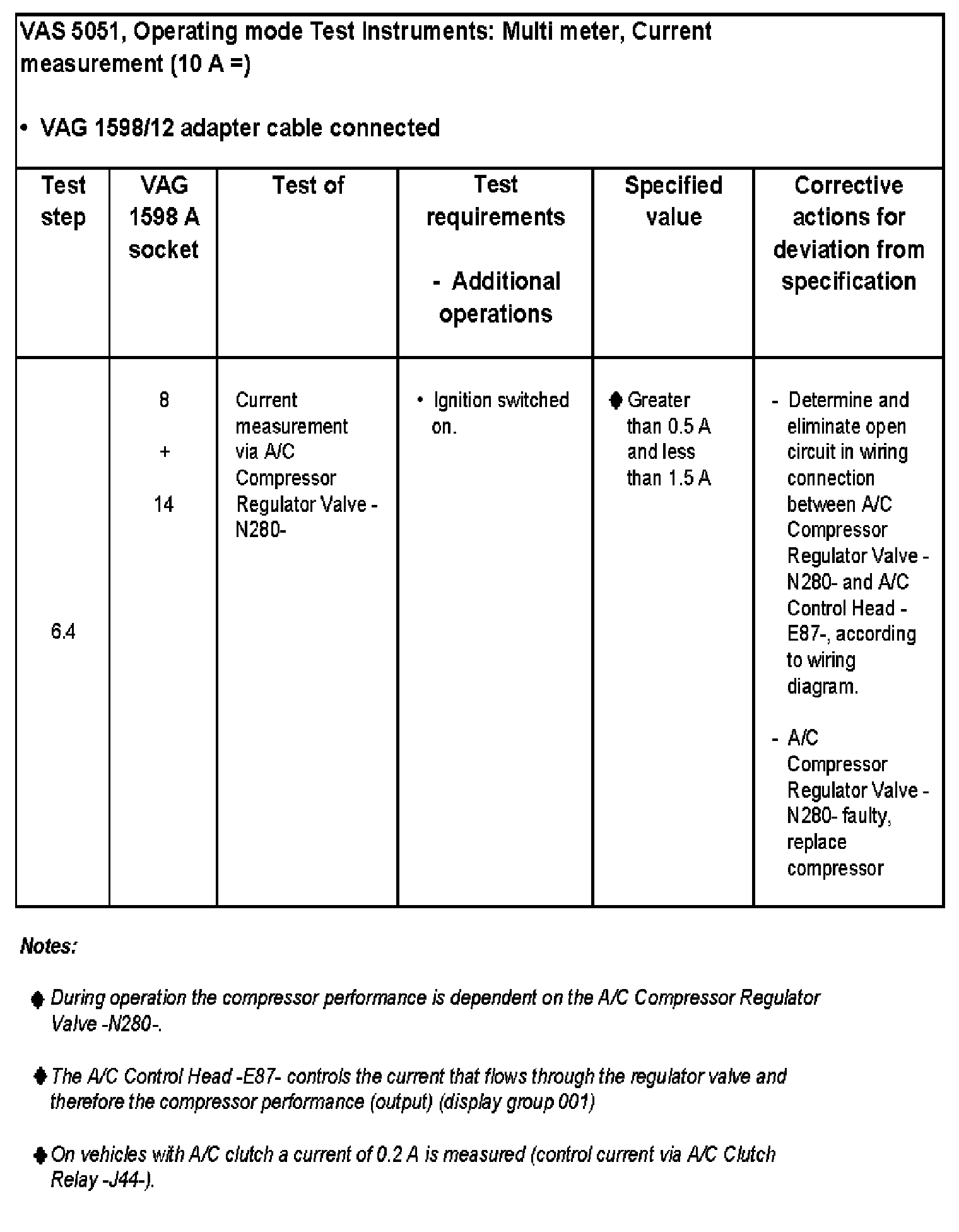
Engagement signal for A/C Compressor Regulator Valve -N280-, checking
- Switch ignition off.
- Connect A/C control head to vehicle wiring harness.
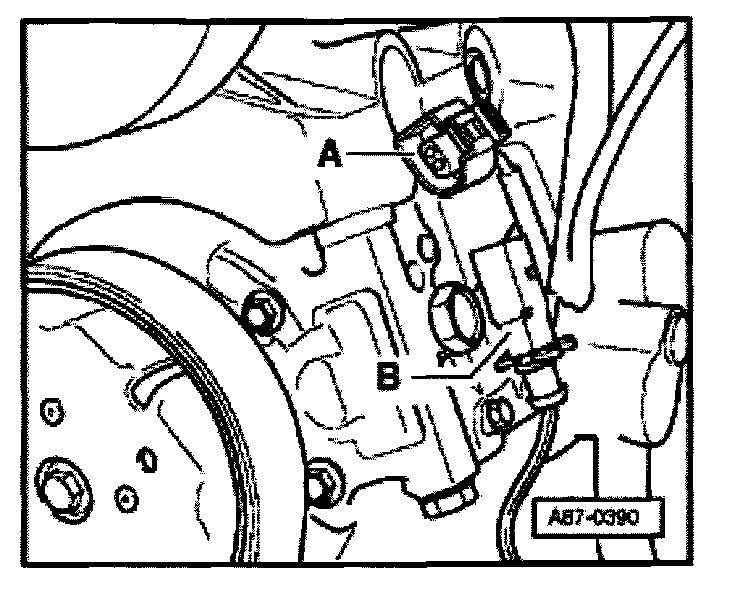
- Disconnect harness connector on A/C compressor.
- Recreate connection to regulator valve between connector -A- and connector -B-, using adapter cable of VAG 1594 A connector test kit.
NOTE:
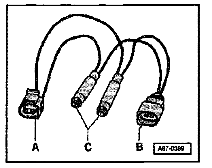
You can create an adapter cable for this test. E.g. use connectors A and B (part number 1J0 973 702 and 1J0 973 802 and relevant terminal contacts), two suitable sockets for connectors C and wires with 0.5 mm 2 diameter.
- Connect DSO-measuring cable VAS 5051/8 to two adapter cable.
- Measuring cable (signal wire) to terminal -2-.
- Measuring cable (shielded, ground) to terminal -1-.
- Select operating mode "Test instrument" on VAS 5051: DSO (Digital Storage Oscilloscope) on
- Setting 5V/Div =, 5ms/Div (5Volt DC voltage and 5 milli seconds per unit)
- Start engine
- Select preset temperature to "Lo" on A/C control head.
- Switch activation of A/C Compressor Regulator Valve -N280- on and off, by pressing the "Auto" and "Econ" button on the A/C Control Head -E87-
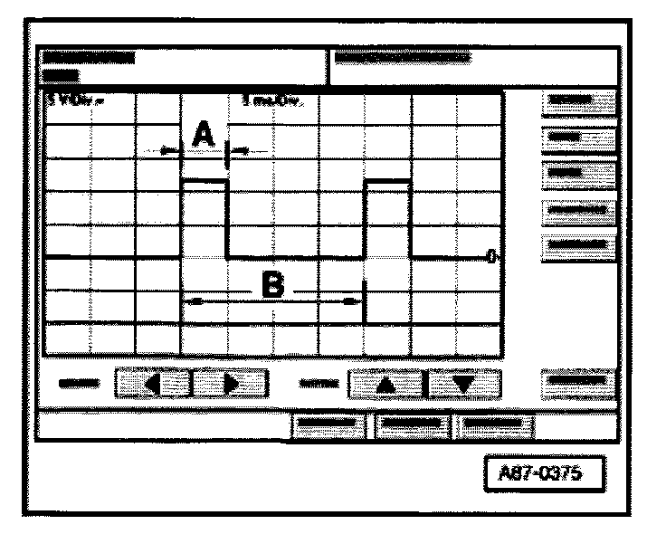
Depending on button pressed on A/C Control Head -E87- the oscilloscope displays:
- During operating mode "OFF" of "Econ" no square wave signal (the regulator valve is not activated).

- During operating mode "Auto" and temperature selection "Lo" a square wave signal with an impulse width -A- between 75% and 100% (the regulator valve is activated)
NOTE:
- The illustration shows a signal with a duty cycle ratio of approx. 80%.
- The impulse width -A- is dependent of the required cooling performance, the vehicle voltage etc. (via the width of range -A- the current is regulated through A/C Compressor Regulator Valve -N280- by the A/C Control Head -E87-.
- The signal distance -B- is always 2 milli seconds (corresponds to frequency of 500 Hertz).
- The duty cycle is determined by the ratio of impulse width -A- and signal distance -B-.
- In the event that you connect the signal cable to terminal -1- and the cable with the Ground connection to vehicle Ground, a mirror image of the shown signal in illustration A87-0374 appears.
- The impulse width of the square wave signal changes depending on A/C Control Head -E87- selection and measured surrounding conditions (duty cycle between 100% and greater than 30%, the control valve is so activated, that the preselected temperature is reached (compressor performance is attained).
NOTE:
- During operating mode "Auto" and temperature selection "Lo" the A/C Compressor Regulator Valve -N280- is activated in such way that the maximum permissible current of 0.65 A flows through -N280- (maximum compressor output).
- In controlled operation, the activation period is dependent on the requested cooling performance, the vehicle voltage etc. The activation period is at least so long that an average current of 0.3 A flows.
Test step 7
A/C Clutch Relay -J44- and activation of A/C clutch -N25-
Test Step 7.1:
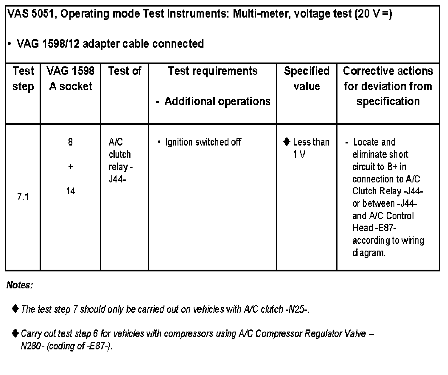
Test Step 7.2:
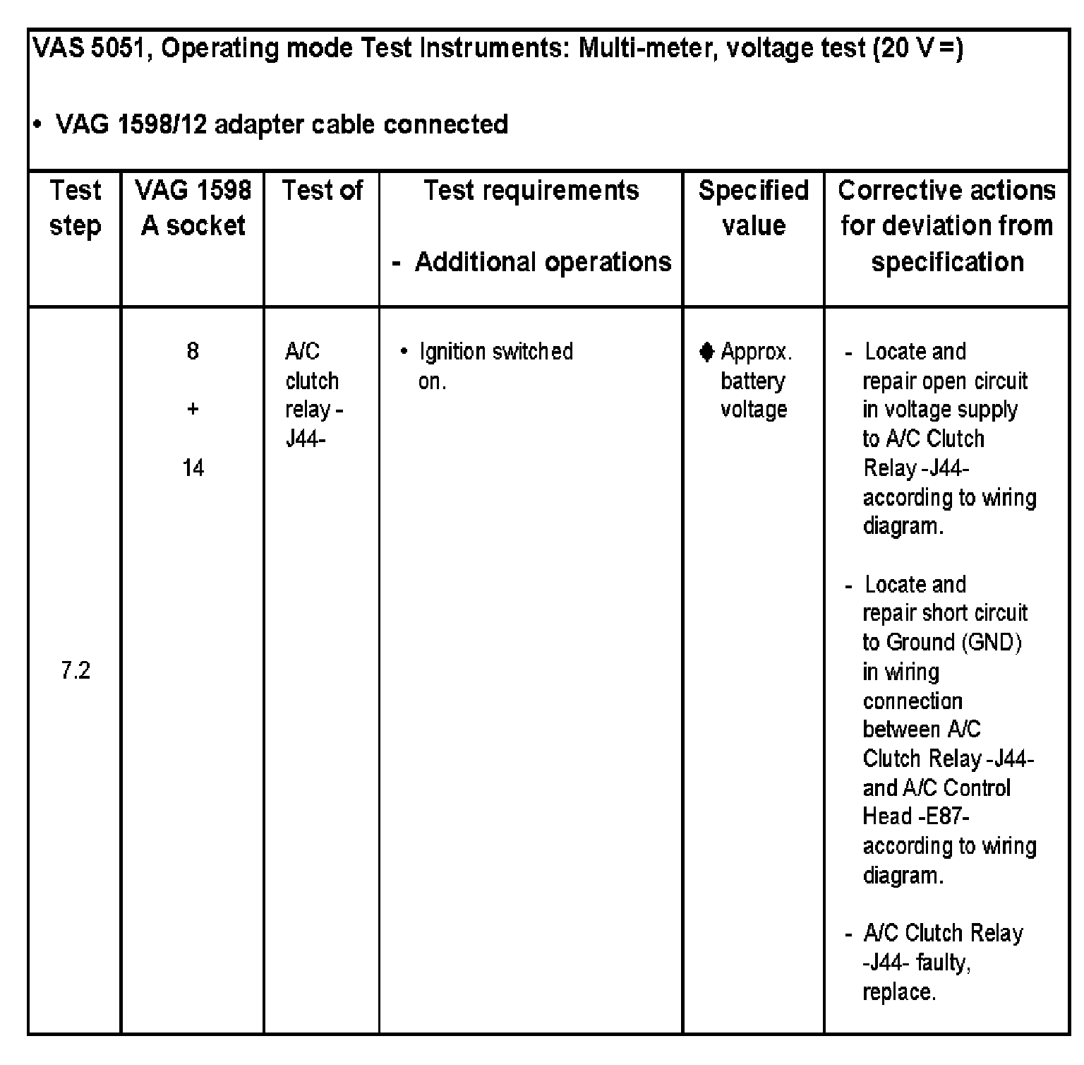
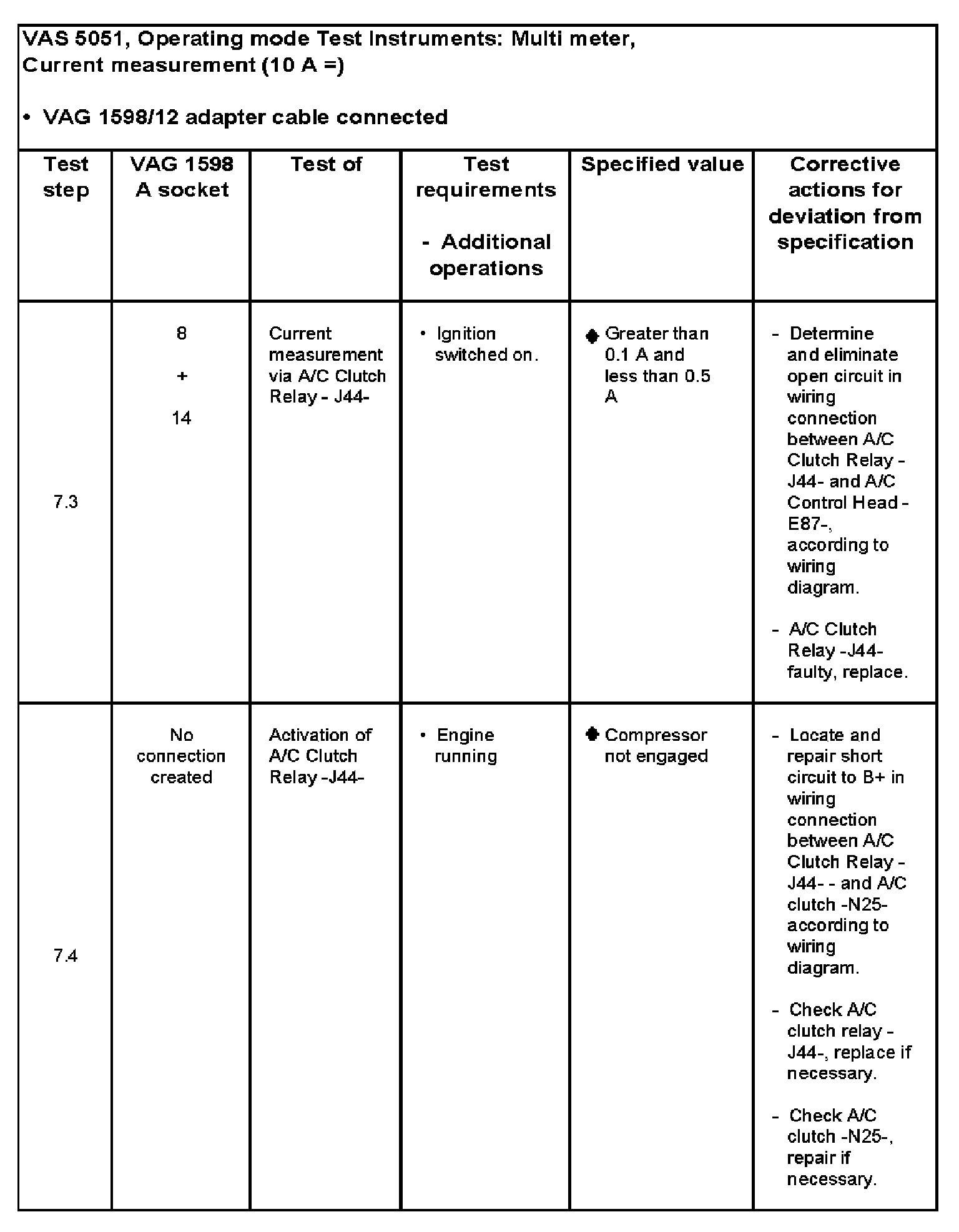
Test Step 7.3 - 7.4:
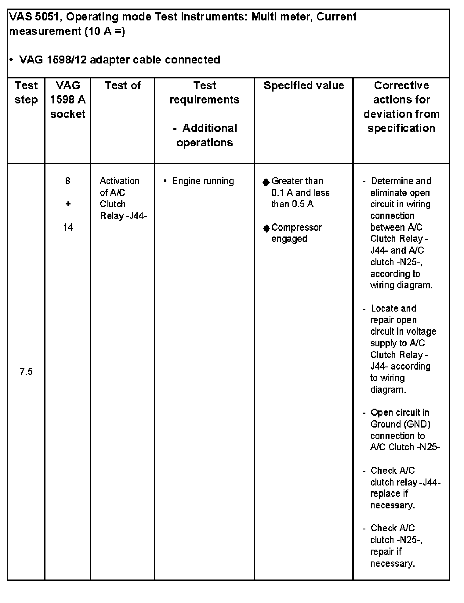
Test Step 7.5:
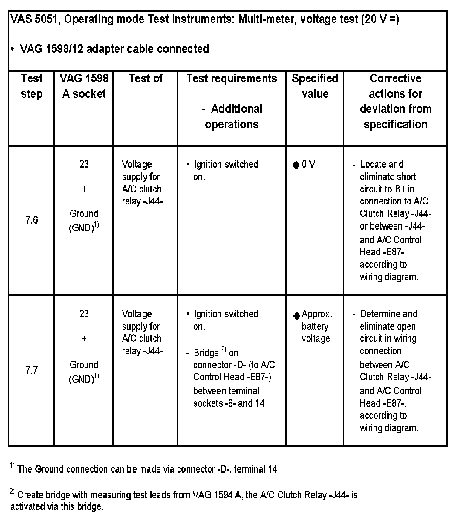
Test Step 7.6 - 7.7:
Test step 8:
Activation of Coolant Fan -V7- (step 1 and 2)
NOTE:
- Test step 8 should only be carried out on the following vehicles:
- Vehicles with compressors using A/C Clutch -N25- and -N280-
- On vehicles with gas engines and A/C Compressor Regulator Valve -N280-, the coolant fan is activated by the A/C Control Head -E87- via the CAN-bus system through the respective Engine Control Module (ECM).
- Depending on engine, the Coolant fan -V7- is activated via Coolant Fan control (FC) Relay -J26- and Second Speed Coolant Fan Control (FC) Relay -J101- or via Coolant FC (Fan Control) Control Module -J293-.
- The Coolant fan -V7- is switched to first speed from Coolant Fan control (FC) Relay -J26-/Coolant FC (Fan Control) Control Module -J293-:
- with Coolant Fan Control (FC) Thermal Switch -F54- closed.
- when A/C Control Head -E87- supplies a Plus signal (as soon as compressor engages).
- The Coolant fan -V7- is switched to second speed by the Second Speed Coolant Fan Control (FC) Relay -J101-/Coolant FC (Fan Control) Control Module -J293-:
- when Coolant Fan Control (FC) Thermal Switch -F18 is closed.
- when A/C Control Head -E87- supplies a Plus signal (as soon as pressure in refrigerant circuit increases 16 bar).
- On vehicles with Coolant FC (Fan Control) Control Module -J293- and depending on version of - J293-, the coolant fan is switched on only with the engine running (plus at terminal "61").
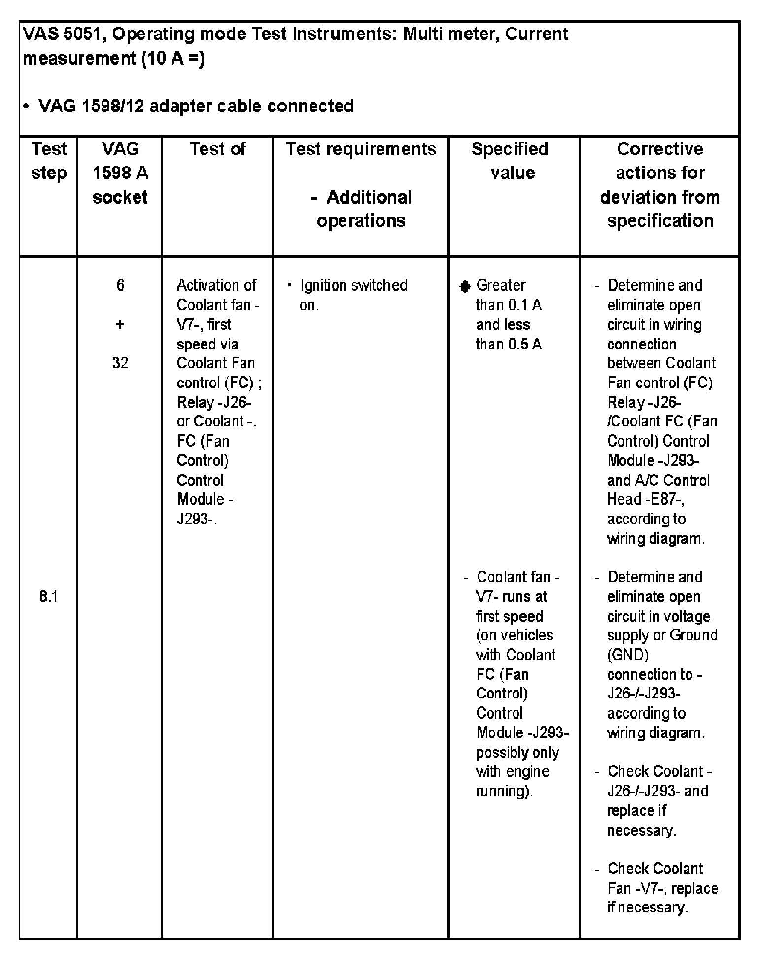
Test Step 8.1:
Test Step 8.2:

Test step 9:
Sunlight Photo Sensor -G107-
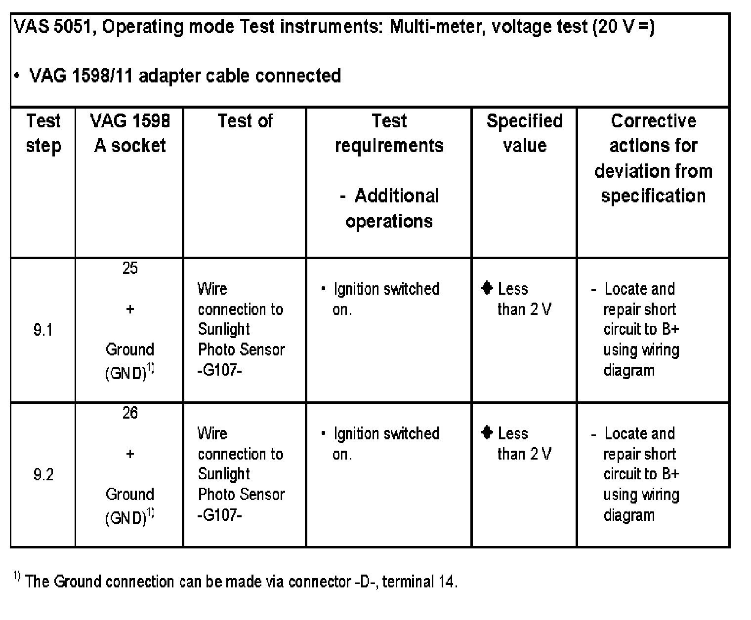
Test Step 9.1 - 9.2:
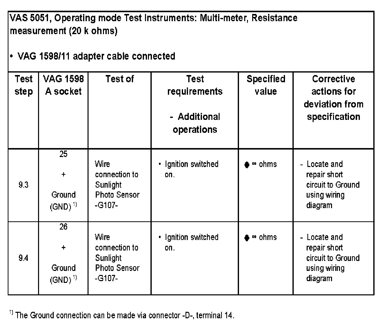
Test Step 9.3 - 9.4:
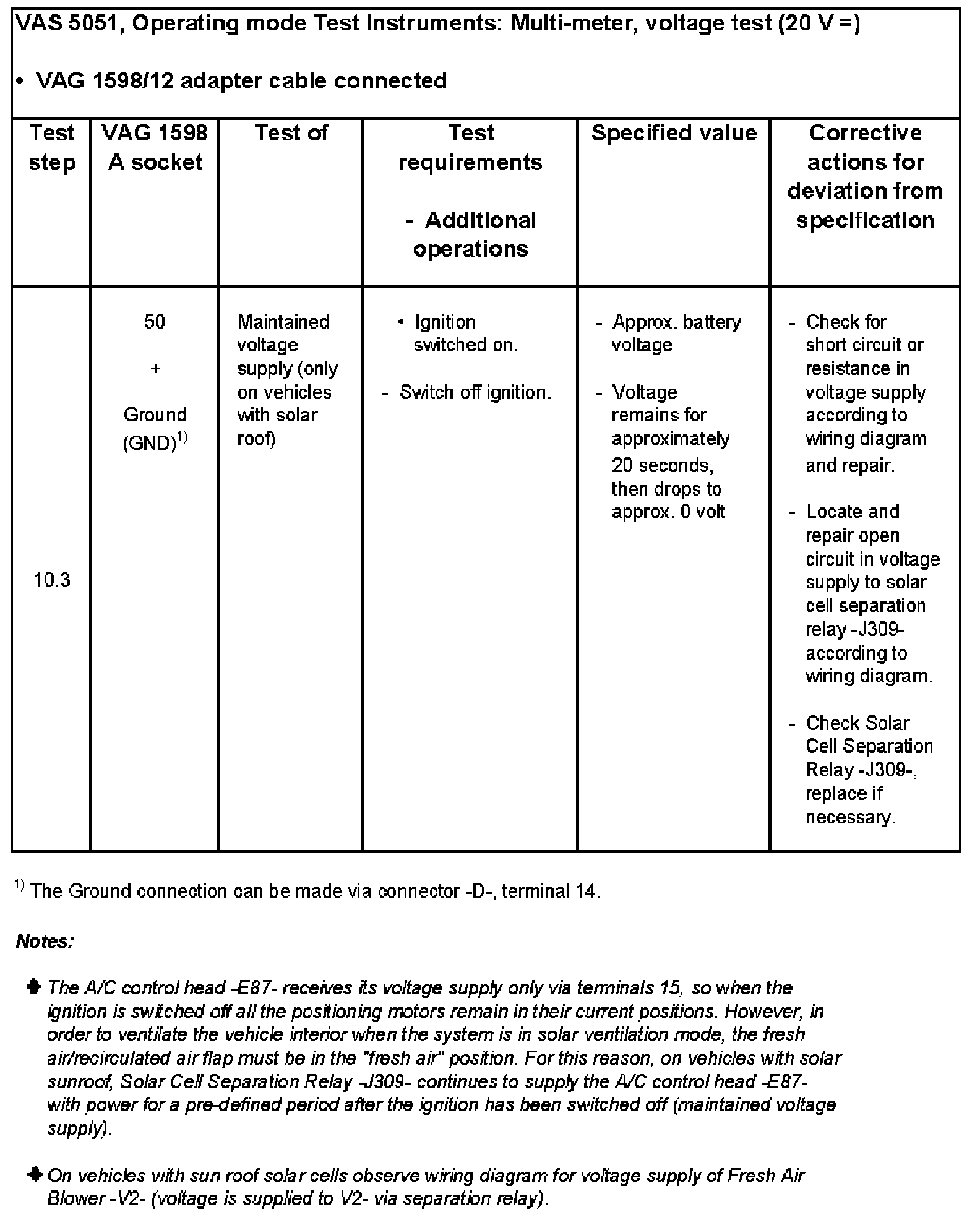
Test step 10:
Input for engagement signal of A/C Control Head -E87- for vehicles with solar cells
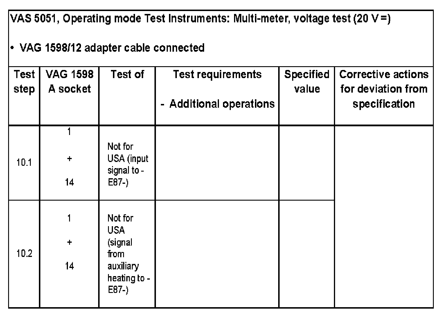
Test Step 10.1 - 10.2:
Test Step 10.3: