Hydraulic Control Assembly, Removing and Installing
Notes:
^ Always replace the hydraulic control assembly if dirty or defective.
Removing
- Remove automatic transmission control module-J217.

- Pull selector lever position slide -C- down out of bearing hole in hydraulic control assembly.
- Disengage spring -A- from selector shaft -D-.
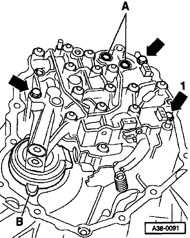
- Unscrew bolts -arrows- and remove hydraulic control assembly.
Installing
Install in reverse order, paying attention to following:

- Replace axial seals -A- (4 pcs.) and -B-.
Notes:
^ Coat the axial seals with ATF before installing them.
^ The axial seals -A- must inserted into the receptacles with the smaller diameter facing the transmission.
- Attach cover -C-. Make sure that locating lug is positioned correctly.
Note: The locating lug on the rear side of the cover must be inserted into the small hole in the transmission surface.
- Push selector shaft lever -2- forward as far as it will go so that selector tab -1- is almost vertical (leaning slightly toward the right).

- At rear of hydraulic control assembly, push control plunger-B- inward (left) as far as it will go until it engages in mounting spring -A-.
- Insert hydraulic control assembly into transmission without tilting it.
Note: When attaching the control assembly, make sure that the selector tab engages in the free slot -arrow- on the control plunger -B-.
- Hand-tighten bolts-arrows-. Bolt arrow 1- is shorter than other two bolts.
- Check cover to make sure that it is fitted correctly. Locating lug -B- must be engaged in locating hole in transmission.

- Checking function of control plunger
- B- Move selector shaft repeatedly to left and right using detent plate -C- or selector shaft lever.
- Control plunger-B- must move outward or inward accordingly -arrow
- If control plunger does not move, selector tab has not engaged in slot -arrow- on control plunger-B- on rear side of hydraulic control assembly. If this is the case, you must remove and install hydraulic control assembly again.
- Tighten bolts -arrows- to 10 Nm.
- Installing selector lever position slide -C"
- Attach roller -B- to selector lever position slide -C- with collar pointing downward.
- Engage spring -A- in selector shaft -D- and selector lever position slide - C-.
- Insert selector lever position slide -C- into bearing hole in housing of hydraulic control assembly.
- Move selector shaft lever -2- forward and backward as far as it will go.
Note: The transmission in the illustration is shown without a hydraulic control assembly.
- Detent plate -arrow- moves forward and backward. Roller -B- must engage in individual grooves. Selector lever position slide -C- moves forward and backward in steps.
Roller -B- must be fitted with collar at bottom so that it cannot be pulled out from above.
- Before installing automatic transmission control module-J217, replace O-rings-A- on hydraulic control assembly.
Note: Coat the O-rings with ATF before inserting them.
- Clean selector shaft.
- Re-install automatic transmission control module -J217-.