Mode 5: Check Oxygen Sensor Output Signals
Mode 5: Check Oxygen Sensor Output Signals
The static values of the oxygen sensors are indicated in this diagnostic mode.
The values of the individual oxygen sensor test results must reach the specified value or must be within the min.- and max.- limits.
Test requirements:
- No DTCs in DTC memory; check DTC memory see "Mode 3: Check DTC memory". Mode 3: Check DTC Memory
- Coolant temperature at least 80 degrees C "Mode 1: Check measuring values "; "PID 05: Coolant temperature". Mode 1: Check Measured Values
Procedure
- Connect diagnostic tester.
- Start engine and let run at idle.
- In diagnostic function "33 - OBD", select "Mode 5: Check output of oxygen sensor signals".
- Using the following table, select the desired output of oxygen sensor signals according to Test ID (Test Identification), e.g. "01: Rich to lean sensor barrier voltage".
- Check specified values at idle.
NOTE:
- Bank 1 = cylinder bank 1 in direction of travel, right; Bank 2 = cylinder bank 2 in direction of travel, left.
- When selecting the diagnostic mode, the entry is always performed in "Bank 1 sensor 1".
- If the Vehicle Diagnostic, Testing and Information System VAS 5051 or the Vehicle Diagnostic and Information System VAS 5052 is used for checking the lambda test results, the respective oxygen sensor can be selected by pressing button 1, 2, 5 and 6:
- Button 1 = Bank 1 sensor 1,
- Button 2 = Bank 1 sensor 2,
- Button 5 = Bank 2 sensor 1,
- Button 6 = Bank 2 sensor 2.
Test- ID1) Diagnostic text
01: Rich to lean sensor barrier voltage
02: Lean to rich sensor barrier voltage
07: Minimum voltage at sensor for test cycle
08: Maximum voltage at sensor for test cycle
129: Current value of oxygen sensor signal
130: Specified value of oxygen sensor signal
131: Dynamic value
132: Shift of oxygen sensor regulation before catalytic converter via oxygen sensor regulation behind catalytic converter
1) Test IDs that are not relevant are not listed.
- End diagnosis and switch ignition off.
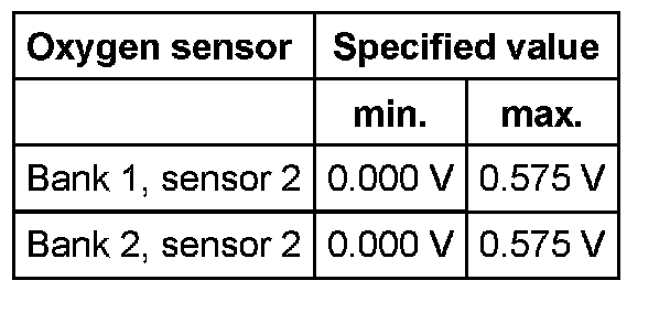
Evaluation test-ID 01: Rich to lean sensor barrier voltage
Oxygen sensor Specified value
Bank 1, sensor 2 0.575 V
Bank 2, sensor 2 0.575 V
If specified value is not obtained:
- Replace respective oxygen sensor behind catalytic converter
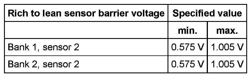
Evaluation test-ID 02: Lean to rich sensor barrier voltage
Oxygen sensor Specified value
Bank 1, sensor 2 0.575 V
Bank 2, sensor 2 0.575 V
If specified value is not obtained:
- Replace respective oxygen sensor behind catalytic converter.
Evaluation test-ID 07: Minimum voltage at sensor for test cycle
If specified value is not reached:
- Short circuit to Ground (GND) in oxygen sensor or in wire.
- Check Oxygen Sensor (O2S) and oxygen sensor control behind Three Way Catalytic Converter (TWC). Check Oxygen Sensor and Oxygen Sensor Control Behind Catalytic Converter
If the specified value is exceeded:
- Oxygen sensor not ready for operation
- Oxygen sensor heating faulty
- Test oxygen sensor heater behind catalytic converter
- Short circuit to B+ or open circuit in wiring in oxygen sensor or in wire.
- Check Oxygen Sensor (O2S) and oxygen sensor control behind Three Way Catalytic Converter (TWC). Check Oxygen Sensor and Oxygen Sensor Control Behind Catalytic Converter
Evaluation test-ID 08: Maximum voltage at sensor for test cycle
If the specification is exceeded or not met:
- Oxygen sensor not ready for operation
- Oxygen sensor heating faulty
- Test oxygen sensor heater behind catalytic converter
- Short circuit to Ground (GND) or B+ or open circuit in wiring in oxygen sensor or in wire.
- Check Oxygen Sensor (O2S) and oxygen sensor control behind Three Way Catalytic Converter (TWC). Check Oxygen Sensor and Oxygen Sensor Control Behind Catalytic Converter
Evaluation test-ID 129: Current value of oxygen sensor signal

1) Control module internal calculated value
If the specification is exceeded or not met:
- Oxygen sensor not ready for operation
- Oxygen sensor heating faulty
- Test oxygen sensor heater before catalytic converter
- Short circuit to Ground (GND) or B+ or open circuit in wiring in oxygen sensor or in wire.
- Oxygen sensor faulty
- Check Oxygen Sensor (O2S) and oxygen sensor control before Three Way Catalytic Converter (TWC). Oxygen Sensors and Oxygen Sensor Control Before Catalytic Converter, Checking
Evaluation test-ID 130: Specified value of oxygen sensor signal

1) Control module internal calculated value
If the specification is exceeded or not met:
- Replace Engine Control Module (ECM).
Evaluation test-ID 131: Dynamic value
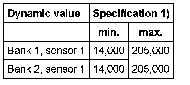
1) Control module internal calculated value
If specified value is not reached:
- Oxygen sensor is aged
- Replace respective oxygen sensor before catalytic converter.
Evaluation test-ID 132: Shift of oxygen sensor regulation before catalytic converter via oxygen sensor regulation behind catalytic converter
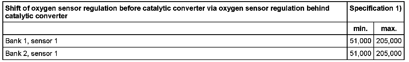
1) Control module internal calculated value
If specified value is not reached:
- Oxygen sensor not ready for operation
- Oxygen sensor heating faulty
- Test oxygen sensor heater before catalytic converter
- Short circuit to Ground (GND) or open circuit in wiring in oxygen sensor or in wire.
- Oxygen sensor faulty
- Check Oxygen Sensors (O2S) and oxygen sensor control before Three Way Catalytic Converter (TWC). Oxygen Sensors and Oxygen Sensor Control Before Catalytic Converter, Checking
- Mixture too rich
- Check fuel pressure regulator and residual pressure. Fuel Pressure Regulator and Holding Pressure, Checking
- Check fuel injectors. Check Fuel Injectors
- Check Evaporative Emission (EVAP) canister purge regulator valve -N80-. Evaporative Emission (EVAP) Canister Purge Regulator Valve -N80-, Checking
If the specified value is exceeded:
- Oxygen sensor not ready for operation
- Oxygen sensor heating faulty
- Test oxygen sensor heater before catalytic converter.
- Short circuit to B+ or open circuit in wiring in oxygen sensor or in wire.
- Oxygen sensor faulty
- Check Oxygen Sensors (O2S) and oxygen sensor control before Three Way Catalytic Converter (TWC). Oxygen Sensors and Oxygen Sensor Control Before Catalytic Converter, Checking
- Mixture too lean
- Check fuel pressure regulator and residual pressure. Fuel Pressure Regulator and Holding Pressure, Checking
- Check fuel injectors. Check Fuel Injectors
- Check intake system for leaks (false air). Intake System For Leaks (False Air), Checking
- Check Fuel Pump (FP). Fuel Pump (FP), Electrical Testing
- Check exhaust system for proper seal. Exhaust System For Proper Seal, Checking
- Check Secondary Air Injection (AIR) system for proper seal. Secondary Air Injection (AIR) System, Checking For Proper Seal
- Check vacuum lines for leaks.
Final procedures
After repair work, the following work steps must be performed in the mentioned sequence:
1. Check DTC memory See "Mode 3: Check DTC memory". Mode 3: Check DTC Memory
2. If necessary, erase DTC memory see "Mode 4: Reset/erase diagnostic data". Mode 4: Reset/Erase Diagnostic Data
3. Generate readiness code. Readiness Code, Generating
- End diagnosis and switch ignition off.