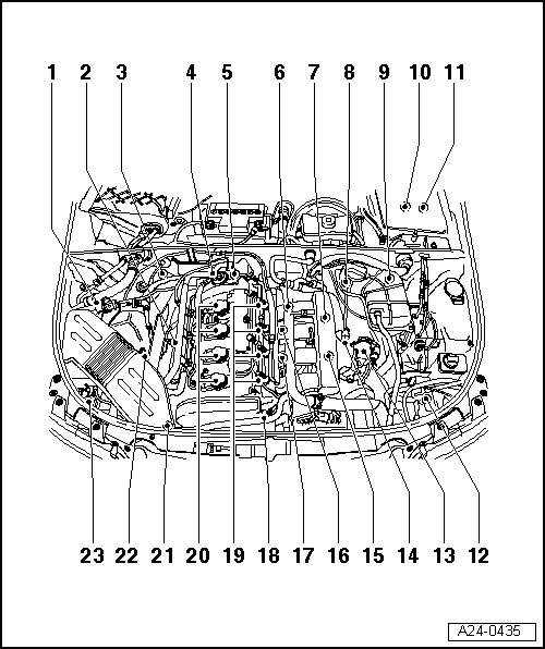
1.8L T AMB
Engine Management System
1.8L T AMB
Component A - F are not shown in the overview
A - Camshaft Adjustment Valve 1 -N205- => [ Camshaft Adjustment Valve 1 ] See Image Below.
B - Leak Detection Pump (LDP) -V144- => [ EVAP Canister/Leak Detection System Overview ] See Image Below.
C - Oil Level Thermal Sensor -G266- => [ Oil Level Thermal Sensor ] See Image Below.
• Located at the bottom of the oil pan
D - Oil Pressure Switch -F1- => [ Oil Filter and Oil Cooler Overview ] See Image Below.
E - Brake Light Switch -F- and Brake Pedal Switch -F47-
• Located in footwell on pedal bracket near brake pedal
F - Clutch Pedal Switch -F36-
• Located in footwell on pedal bracket near brake pedal
1 - Evaporative Emission (EVAP) Canister Purge Regulator Valve 1 -N80- => [ EVAP Canister Purge Regulator Valve ] See Image Below.
2 - Heated Oxygen Sensor (HO2S) -G39-
• 1.8L T AMB Exhaust System location => [ 1.8L T AMB Exhaust System ] Exhaust System
3 - Oxygen Sensor (O2S) Behind Three Way Catalytic Converter (TWC) -G130-
• 1.8L T AMB Exhaust System location => [ 1.8L T AMB Exhaust System ] Exhaust System
4 - Combi valve for secondary air inlet
5 - Engine Coolant Temperature (ECT) Sensor -G62- => [ Engine Coolant Temperature (ECT) Sensor ] See Image Below.
6 - Engine Speed (RPM) Sensor -G28- => [ Engine Component Connectors ] See Image Below.
7 - Secondary Air Injection (AIR) Solenoid Valve -N112-
• 1.8L T AMB Exhaust System location => [ 1.8L T AMB Exhaust System ] Exhaust System
• Located below the intake manifold
8 - Bracket for connectors
• Accessible with coolant expansion tank removed and moved to side
9 - Bracket for connectors
• Accessible with coolant expansion tank removed and moved to side
10 - Electronics box (plenum chamber)
• With Motronic Engine Control Module (ECM) -J220- and Barometric Pressure (BARO) Sensor -F96-
• With Motronic Engine Control Module (ECM) Power Supply Relay -J271-
1.8L T AMB continued
11 - Electronics box (plenum chamber)
• With Secondary Air Injection (AIR) Pump Relay -J299-
• 1.8L T AMB Exhaust System location => [ 1.8L T AMB Exhaust System ] Exhaust System
12 - Charge Air Pressure Sensor -G31- => [ Charge Air Pressure Sensor ] See Image Below.
• Located and installed on top of charge air cooler
13 - Throttle Valve Control Module -J338- => [ Fuel Rail with Injectors ] See Image Below.
The Throttle control Module is integrated with the following:
• Throttle Drive (for Electronic Power Control (EPC)) -G186-
• Throttle Drive Angle Sensor 1 (for Electronic Power Control (EPC) -G187-
• Throttle Drive Angle Sensor 2 (for Electronic Power Control (EPC) -G188-
14 - Intake Air Temperature (IAT) Sensor -G42- => [ Fuel Rail with Injectors ] See Image Below.
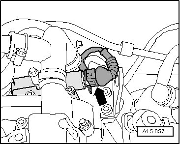
15 - Turbocharger Recirculating Valve -N249- => [ Recirculating valve for turbocharger ] See Image Below.
• Located underneath the intake line
16 - Knock Sensor 1 -G61- => [ Engine Component Connectors ] See Image Below.
17 - Knock Sensor 2 -G66- => [ Engine Component Connectors ] See Image Below.
18 - Camshaft Position (CMP) Sensor -G40- => [ Camshaft Position (CMP) Sensor ] See Image Below.
19 - Fuel Injectors => [ Fuel Rail with Injectors ] See Image Below.
• Cylinder 1 Fuel Injector -N30- , Cylinder 2 Fuel Injector -N31- , Cylinder 3 Fuel Injector -N32- and Cylinder 4 Fuel Injector -N33-
20 - Ignition Coils
• Ignition Coil 1 with Power Output Stage -N70- , Ignition Coil 2 with Power Output Stage -N127- , Ignition Coil 3 with Power Output Stage -N291- and Ignition Coil 4 with Power Output Stage -N292-
21 - Wastegate Bypass Regulator Valve -N75- => [ Turbocharger Component Overview ] See Image Below.
22 - Mass Air Flow (MAF) Sensor -G70- => [ Mass Air Flow (MAF) Sensor ] See Image Below.
23 - Secondary Air Injection (AIR) Pump Motor -V101-
• Located front right in the engine compartment below the longmember
• 1.8L T AMB Exhaust System location => [ 1.8L T AMB Exhaust System ] Exhaust System
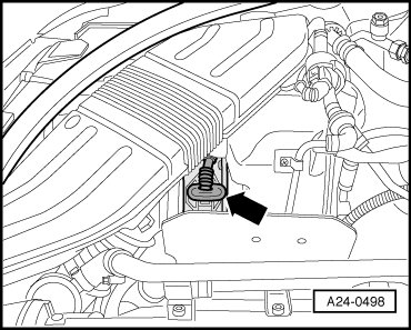
Engine Coolant Temperature (ECT)
Sensor
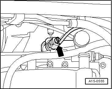
Arrow - Engine Coolant Temperature (ECT) Sensor -G62- with Engine Coolant Temperature (ECT) Gauge Sensor -G2-
Engine Component Connectors
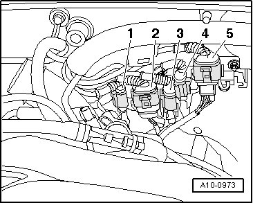
1 - Knock Sensor 1 -G61- connector
3 - Engine Speed (RPM) Sensor -G28- connector
4 - Knock Sensor 2 -G66- connector
EVAP Canister Purge Regulator
Valve
- - Evaporative Emission (EVAP) Canister Purge Regulator Valve 1 -N80- connector
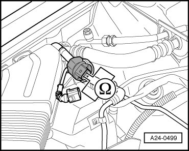
Charge Air Pressure Sensor
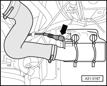
Arrow - Charge Air Pressure Sensor -G31-
- Installed top of the charge air cooler
Fuel Rail with Injectors
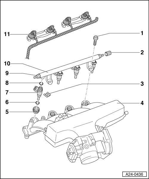
4 - Intake Manifold with Throttle Valve Control Module -J338- and Intake Air Temperature (IAT) Sensor -G42-
7 - Fuel injectors
• Cylinder 1 Fuel Injector -N30-
• Cylinder 2 Fuel Injector -N31-
• Cylinder 3 Fuel Injector -N32-
• Cylinder 4 Fuel Injector -N33-
10 - Fuel Rail
Recirculating valve for turbocharger
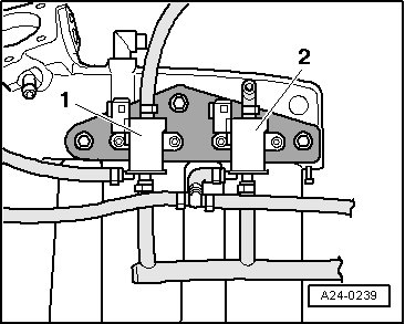
2 - Turbocharger Recirculating Valve -N249-
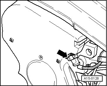
Camshaft Adjustment Valve 1
Arrow - Camshaft Adjustment Valve 1 -N205-
Camshaft Position (CMP) Sensor
Arrow - Camshaft Position (CMP) Sensor -G40-
Turbocharger Component Overview
12 - Wastegate Bypass Regulator Valve -N75-
Mass Air Flow (MAF) Sensor
Arrow - Mass Air Flow (MAF) Sensor -G70-
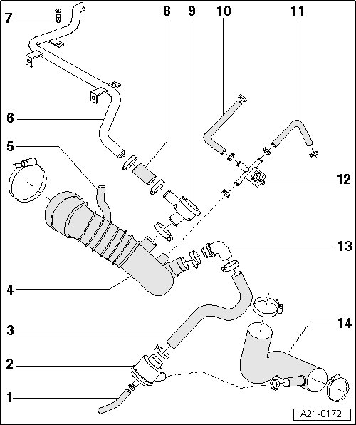
EVAP Canister/Leak Detection System
Overview

6 - Vent line to Evaporative Emission (EVAP) Canister Purge Regulator Valve -N80-
11 - Leak Detection Pump (LDP) -V144-
- Located in the left rear wheel housing behind wheel housing liner
18 - EVAP canister
- Located at the bottom of spare wheel well
Oil Level Thermal Sensor
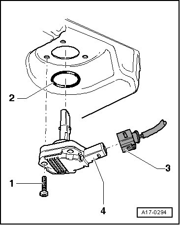
3 - Electrical harness connector
4 - Oil Level Thermal Sensor -G266-
Oil Filter and Oil Cooler Overview
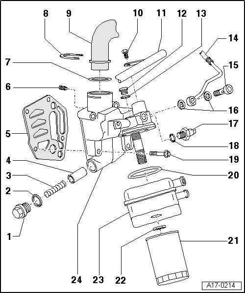
17 - Oil Pressure Switch -F1-
Map Controlled Engine Cooling Thermostat
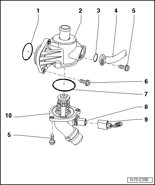
10 - Map Controlled Engine Cooling Thermostat -F265-