Diagram 59/1
Radio / Navigation system (RNS-D), from 2004 m. y.
IMPORTANT NOTE:
This manufacturer uses "Track" style wiring diagrams.
For information on how to use these diagrams effectively, please refer to Diagram Information and Instructions. Diagram Information and Instructions
Main fuse
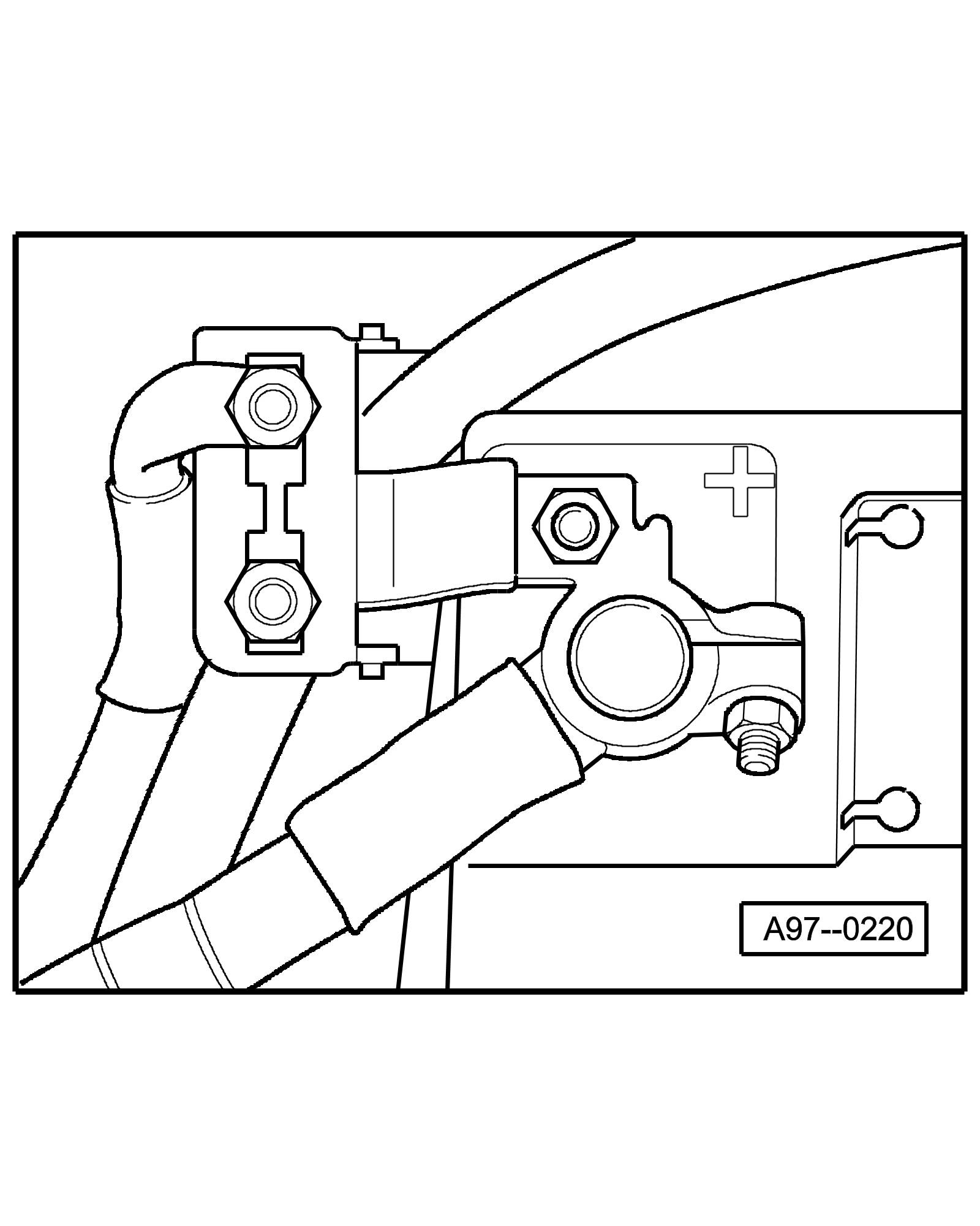
• on the Battery
Fuse holder
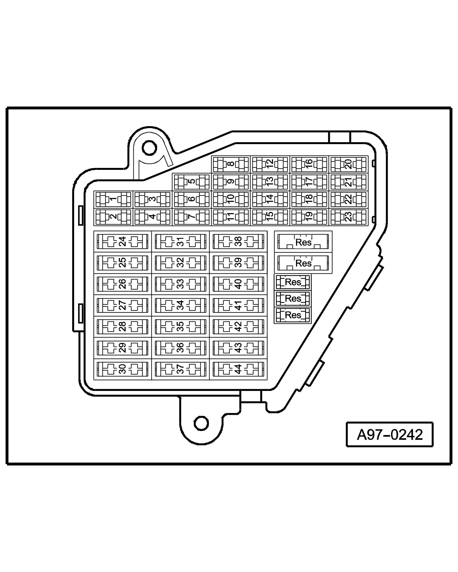
• Instrument panel driver side
Fuse Colors
30 A - Green
25 A - Withe
20 A - Yellow
15 A - Blue
10 A - Red
7,5 A - Brown
5 A - Beige
Note::
• Fuse in fusebox from 23 onwards are numbered 223 onwards in Current Flow Diagram.
Coupling station with threaded connection

• in the electronics box, plenum chamber
3 - 17-Pin Connector, red (T17d)
Connector station A-pillar

• behind side trim, left
9 - 17-Pin Connector, dark brown (T17g)
15 - 17-Pin Connector, green (T17b)
17 - 17-Pin Connector, black (T17)
4-Pin Relay Carrier with threaded connection

• Instrument panel driver side
Next Diagram 59/2 (Tracks 1-14)