Connectors, BOSE 6000 Sound System
BOSE 6000 Sound System
Digital Sound System Control Module (J525)
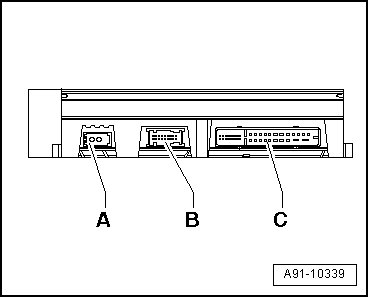
A MOST Bus
B 18-pin multi-pin connector, not used
C Black 32-pin multi-pin harness connector (T32f)
• Unlisted connector terminals are not assigned.
A - MOST Bus
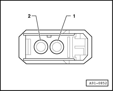
1. Input
2. Output
C - Black 32-pin multi-pin harness connector (T32f)

1 Terminal 30
2 Terminal 31
3 Loudspeaker, right front (-)
4 Loudspeaker, right front (+)
5 Left front bass speaker (R21) (+)
7 Loudspeaker, left front (-)
8 Loudspeaker, left front (+)
9 Microphone input 1 (-) from microphone unit in front roof module (R164) (interior microphone)
10 Microphone input 1 (+) from microphone unit in front roof module (interior microphone)
11 Speaker in rear shelf (R150) (-)
12 Speaker in rear shelf (+)
13 Center mid-treble speaker (R158) (-)
14 Center mid-treble speaker (+)
15 Right front bass speaker (R23) (-)
16 Right front bass speaker (+)
17 Left front bass speaker (-)
19 Loudspeaker, right rear (-)
20 Loudspeaker, right rear (+)
21 Loudspeaker, left rear (-)
22 Loudspeaker, left rear (+)
23 microphone unit in front roof module (shielding)
24 Microphone 2 (-) from microphone unit in front roof module (speech recognition system microphone (R206)) through 29 August 2008
25 Microphone 2 (+) from microphone unit in front roof module (speech recognition system microphone) through 29 August 2008
29 Ring-break diagnostic wire
30 NF (-) from cell phone preparation preliminary setup/Japan Nav/China Nav
31 NF (+) from cell phone preparation preliminary setup/Japan Nav/China Nav