Fuel Injector: Service and Repair
Fuel Injectors
Special tools, testers and auxiliary items required
• Torque Wrench (V.A.G 1331)
• SW 17 socket (V.A.G 1331/6)
• SW 14 socket, open ring (V.A.G 1331/8)
• Tool set (T10133) with (T10133/10)
Removing
CAUTION!
• Fuel system is under high pressure! Before opening high pressure components of the fuel injection system, pressure must be relieved to residual pressure. Refer to => [ Before Opening High Pressure Fuel Injection System ] Service and Repair.
• Then wrap a clean rag around the connection and relieve residual pressure by carefully loosening the connection.
- Remove intake manifold. Refer to => [ Intake Manifold ] Intake Manifold.
• Seal intake channels in cylinder heads with a clean cloth.
- Disconnect electrical harness connectors at fuel injectors.
- Remove high pressure line - 1 - from connector on fuel rail.
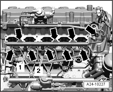
- Remove high pressure line - 2 - from connector on fuel rail. To do this, counterhold at hex head with and open-end wrench and loosen the union nut.
- Remove bolts - arrows -.
• Illustration depicts left cylinder head.
• Do not change the angles of the high pressure lines.
- Remove fuel rail with fuel injectors.
If the fuel injectors cannot be pulled out of the cylinder head by hand, proceed as follows:
- Using a screwdriver, bend the retaining tabs - 1 - of the radial adjustment aside - arrow - and pull the support ring - 2 - from the fuel injector.

- Remove O-ring from fuel injector.
- Guide the Adapter (T10133/10) into the groove of the fuel injector and carefully drive the fuel injector out.
- Guide the puller (T10133/2A) in the groove on the fuel injector.

- Then position the trim removal wedge (T10133/16) and remove the fuel injector by loosening bolt - 1 -.
• When setting the puller in place, the radial adjustment can be destroyed, because the retaining tabs break.
• The combustion chamber seal must always be replaced before re-installing the high-pressure fuel injector.
Teflon Combustion Chamber Seal, Removing and Installing
- Carefully remove the old Teflon seal - arrow - with the appropriate tool (e.g. cut the seal open with a razor and spread seal open with a small screwdriver and pull it forward and off.) When doing this, make sure not to damage the groove and circumferential rib in the groove base.

• If the groove is damage, the fuel injector must be replaced.
Installing
• Replace combustion chamber seal and O-ring.
• Replace spacer ring if damaged.
• Lightly coat fuel injector O-rings with clean engine oil.
• Re-insert injector lines at same cylinder.
- Clean the hole in the cylinder head with the nylon cylinder brush (T10133/4).

- Clip the radial adjustment - 1 - to the support ring - 2 -.

- When re-installing a fuel injector, use a clean cloth to clean combustion residue from the groove for combustion chamber seal and the shaft of the fuel injector.
- Place the assembly cone (T10133/5) with the new combustion chamber seal - 1 - onto the fuel injector - 2 -.

- Push the combustion chamber seal as fast possible onto the assembly cone (T10133/5) using the assembly sleeve (T10133/6).

- Turn the assembly sleeve (T10133/6) around and push the combustion chamber seal into the groove.
• When pushing the combustion chamber seal onto the fuel injector, the seal spreads open. Therefore after pushing it on, it must be tightened again in 2 steps, as follows.
- Press calibrating sleeve (T10133/7) using a gentle turning motion (approximately 180°) on to fuel injector until it stops.

- Pull sizing sleeve (T10133/7) off again, turning it in the opposite direction.
- Press sizing sleeve (T10133/8) with a slight turning motion (approximately 180°) onto the fuel injector until it stops.

- Pull off calibrating (T10133/8) again using turning motion in opposite direction.
- Moisten new O-ring with clean engine oil before installing.
• The combustion chamber seal must not be oiled.
- Using the assembly drift (T10133/9), press the fuel injector into the hole in the cylinder head until it stops.

• The fuel injector must not be difficult to install. If necessary, wait as the combustion chamber seal continues to pull itself together.
- Make sure fuel injectors are correctly positioned in cylinder head.
• The electrical connection of the fuel injector must engage in the intended recess of the cylinder head.
- Press fuel rail onto the fuel injectors with uniform pressure.
- Fasten bolts - arrows - in a diagonal sequence and in steps.
• High pressure line connections must not show any signs of damage.
• Do not change the angles of the high pressure lines.

- Hand-tighten the union nuts for the high-pressure lines.
- Make sure the high-pressure lines are seated free of stress.
- To fasten the SW 14 union nut for high pressure line, use torque wrench (V.A.G 1331) with 17 mm open end wrench socket (V.A.G 1331/8).
- To tighten SW 17 union nut for high pressure line, use the torque wrench (V.A.G 1331) with SW 17 socket (V.A.G 1331/6).

- Only install retaining tabs after high pressure lines have been tightened.
Further installation is in reverse order of removal, note the following:
- Install intake manifold. Refer to => [ Intake Manifold ] Intake Manifold.
- Fill with coolant.
Tightening Specifications
