Diagram 105/3 (Tracks 15-28)
IMPORTANT NOTE:
This manufacturer uses "Track" style wiring diagrams.
For information on how to use these diagrams effectively, please refer to Diagram Information and Instructions. Diagram Information and Instructions
Cellular Telephone Preparation
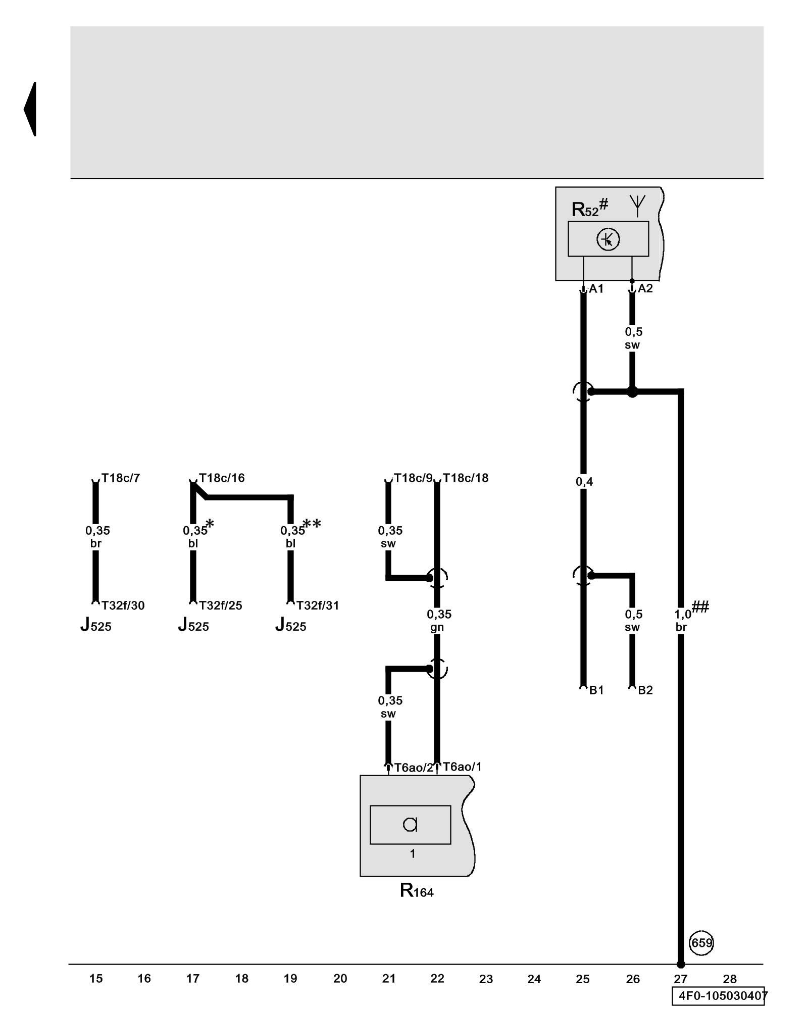
ws = white
sw = black
ro = red
br = brown
gn = green
bl = blue
gr = grey
li = lilac
ge = yellow
or = orange
rs = pink
J525 - Digital Sound System Control Module Overview of Control Modules
R52 - Antenna for Radio, Telephone, Navigation System Locations
R164 - Microphone Unit (in front roof module) Phone System Component Locations
T6ao - 6-Pin Connector, blue, roof module microphone connector
T18c - 18-Pin Connector, black, behind glove compartment
T32f - 32-Pin Connector, black (Connector A), on digital sound system control module
(659) - Ground Connection 1 (right, near rear window) Overview of Ground Connections in Interior of Vehicle
* - Models with DSP sound system (9VD)
** - Models with sound system BOSE (8RY)
# - Roof Antenna
## - Only sedan
Previous Diagram 105/2 (Tracks 1-14)