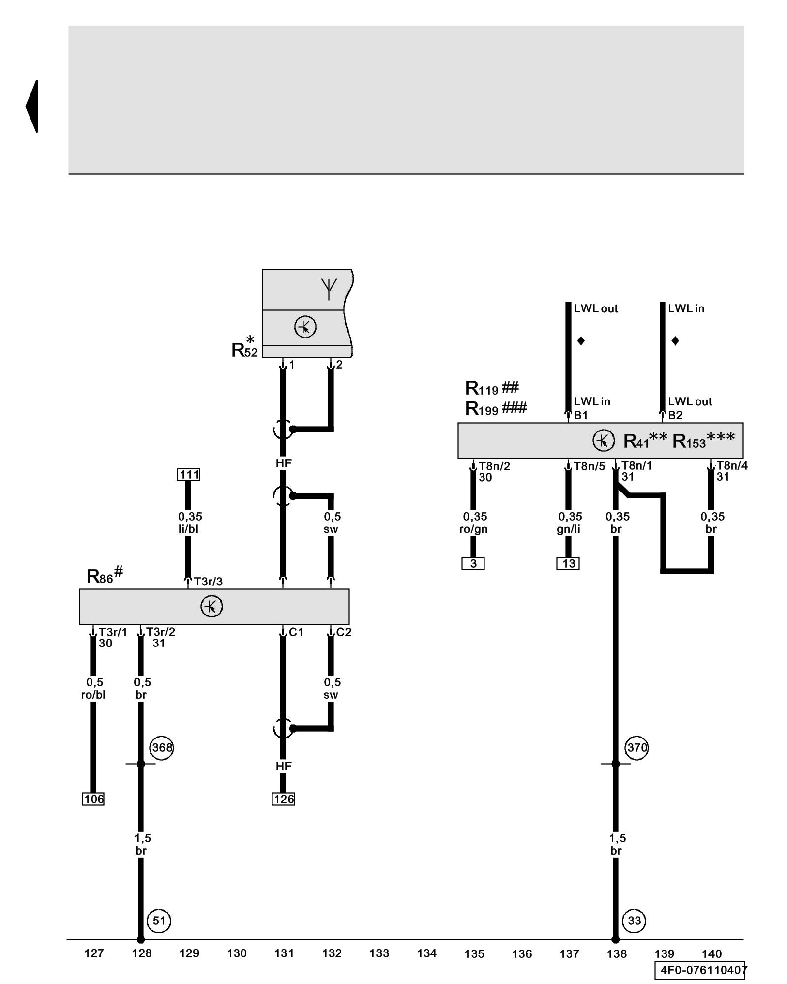
Diagram 76/11 (Tracks 127-140)
IMPORTANT NOTE:
This manufacturer uses "Track" style wiring diagrams.
For information on how to use these diagrams effectively, please refer to Diagram Information and Instructions. Diagram Information and Instructions
Amplifier for Telephone, Antenna for Radio, Telephone, Navigation System, Media Player, Position 2
ws = white
sw = black
ro = red
br = brown
gn = green
bl = blue
gr = grey
li = lilac
ge = yellow
or = orange
rs = pink
R41 - CD Changer Overview of Control Modules
R52 - Antenna for Radio, Telephone, Navigation System Locations
R86 - Amplifier for Telephone Overview of Control Modules
R119 - Media Player, Position 2 Overview of Control Modules
R153 - Mini Disk Player Overview of Control Modules
R199 - External Audio Source Connector
T3r - 3-Pin Connector, black, on amplifier for telephone
T8n - 8-Pin Connector, black, on media player, position 2
(33) - Ground Connection (behind instrument panel, right) Overview of Ground Connections in Interior of Vehicle
(51) - Ground Connection (in luggage compartment, right) Overview of Ground Connections in Interior of Vehicle
(368) - Ground Connection 3 (in main wiring harness)
(370) - Ground Connection 5 (in main wiring harness)
(371) - Ground Connection 6 (in main wiring harness)
* - Roof Antenna
** - Models with CD changer
*** - Models with mini disk player
# - Models with cellular telephone preparation
## - Through October 2006
### - From November 2006
♦ - FOC - Fibre Optic Conductor => Wiring Diagram Infotainment-Data Bus (Most-Ring)
Previous Diagram 76/10 (Tracks 113-126)