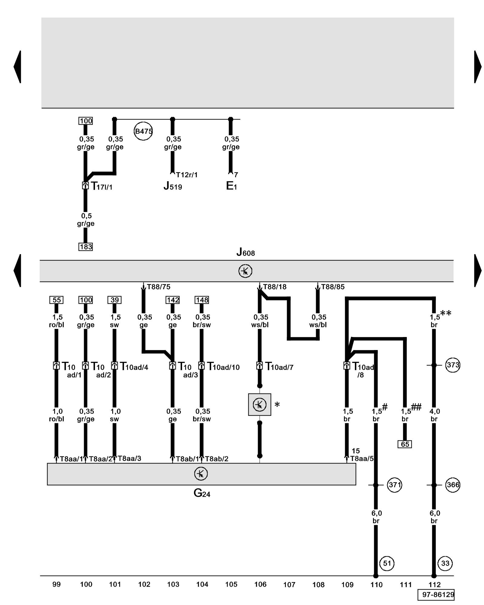
Diagram 48/9 (Tracks 99-112)
IMPORTANT NOTE:
This manufacturer uses "Track" style wiring diagrams.
For information on how to use these diagrams effectively, please refer to Diagram Information and Instructions. Diagram Information and Instructions
Special Purpose Vehicle Control Module, Trip Odometer
ws = white
sw = black
ro = red
br = brown
gn = green
bl = blue
gr = grey
li = lilac
ge = yellow
or = orange
rs = pink
E1 - Light Switch
G24 - Trip Odometer
J519 - Vehicle Electrical System Control Module Overview of Control Modules
J608 - Special Purpose Vehicle Control Module
T8aa - 8-Pin Connector, on trip odometer
T8ab - 8-Pin Connector, on trip odometer
T10ad - 10-Pin Connector, black, interchange connector trip odometer
T12r - 12-Pin Connector, black (Connector B), on vehicle electrical system control module
T17l - 17-Pin Connector, brown, connector station A-pillar, right Overview of Connector Stations and Connectors
T88 - 88-Pin Connector, black, on special purpose vehicle control module
(33) - Ground Connection (behind instrument panel, right) Overview of Ground Connections in Interior of Vehicle
(51) - Ground Connection (in luggage compartment, right) Overview of Ground Connections in Interior of Vehicle
(366) - Ground Connection 1 (in main wiring harness)
(371) - Ground Connection 6 (in main wiring harness)
(373) - Ground Connection 8 (in main wiring harness)
(B475) - Connection 11 (in main wiring harness)
* - V Signal Coding
** - Phased-in modification
# - Through October 2005
## - From November 2005
Previous Diagram 48/8 (Tracks 85-98)
Next Diagram 48/10 (Tracks 113-126)