Diagram 94/7 (Tracks 71-84)
IMPORTANT NOTE:
This manufacturer uses "Track" style wiring diagrams.
For information on how to use these diagrams effectively, please refer to Diagram Information and Instructions. Diagram Information and Instructions
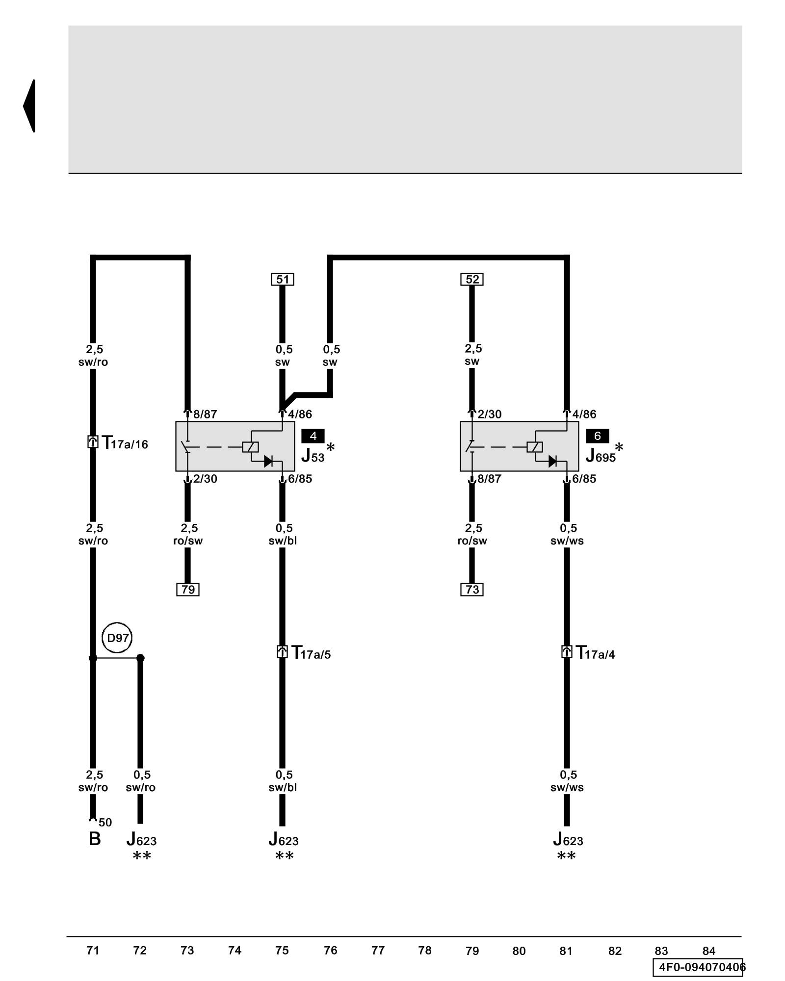
Starter Relay, Starter Relay 2
ws = white
sw = black
ro = red
br = brown
gn = green
bl = blue
gr = grey
li = lilac
ge = yellow
or = orange
rs = pink
B - Starter
J53 - Starter Relay Overview of Relay Carrier
J623 - Engine Control Module (ECM) Overview of Control Modules
J695 - Starter Relay 2 Overview of Relay Carrier
T17a - 17-Pin Connector, red, connector station electronics box in left plenum chamber Overview of Connector Stations and Connectors
(D97) - Connection (50) (in right engine compartment wiring harness)
* - 9-Pin relay carrier, behind driver's storage compartment
** - => Wiring Diagram Engine
Previous Diagram 94/6 (Tracks 57-70)