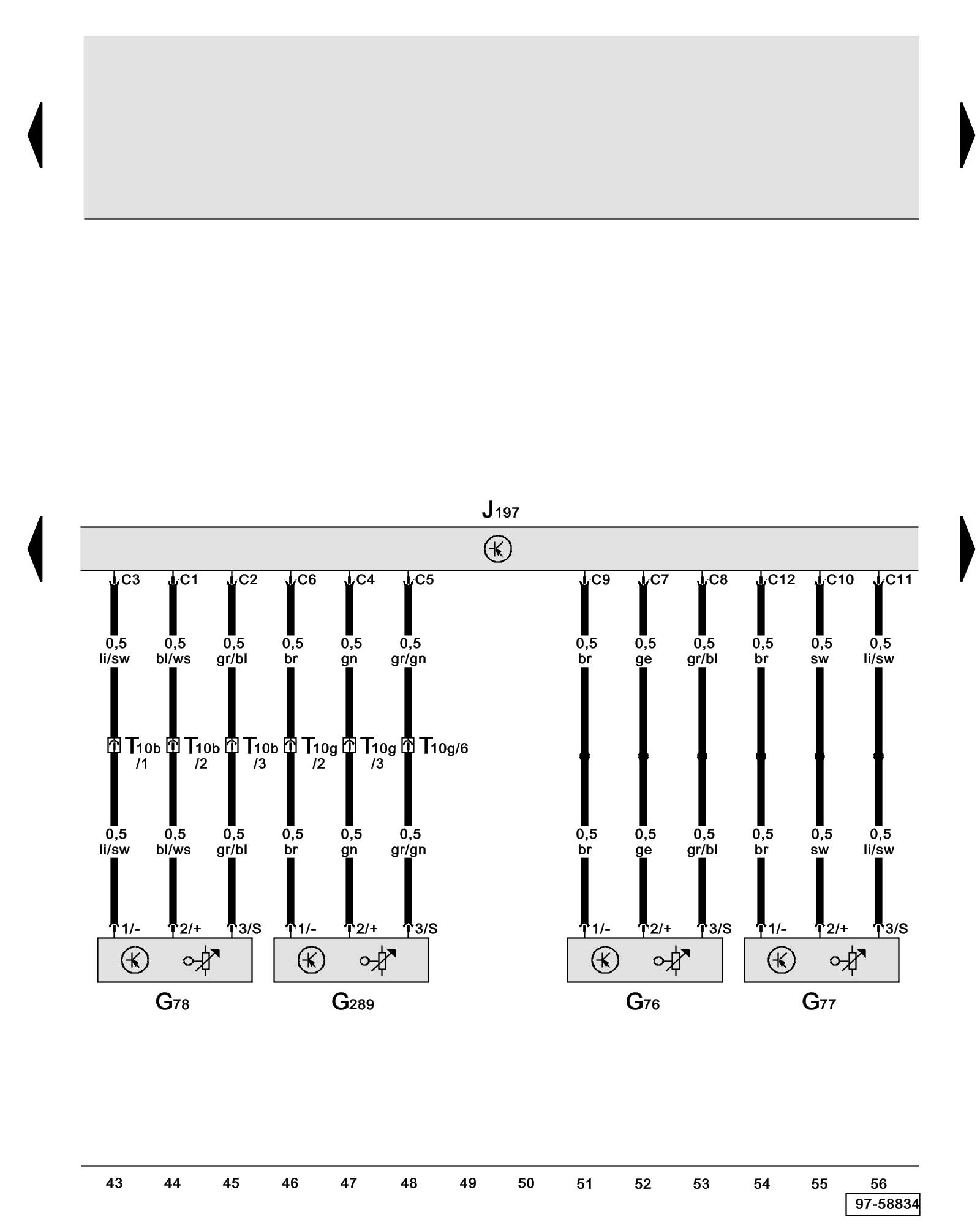
Diagram 19/5 (Tracks 43-56)
IMPORTANT NOTE:
This manufacturer uses "Track" style wiring diagrams.
For information on how to use these diagrams effectively, please refer to Diagram Information and Instructions. Diagram Information and Instructions
Level Control System Control Module, Level Control System Sensor
ws = white
sw = black
ro = red
br = brown
gn = green
bl = blue
gr = grey
li = lilac
ge = yellow
or = orange
rs = pink
G76 - Left Rear Level Control System Sensor Self Leveling Suspension
G77 - Right Rear Level Control System Sensor Self Leveling Suspension
G78 - Left Front Level Control System Sensor Self Leveling Suspension
G289 - Right Front Level Control Sensor Self Leveling Suspension
J197 - Level Control System Control Module Overview of Control Modules
T10b - 10-Pin Connector, blue, connector station A-pillar, left Overview of Connector Stations and Connectors
T10g - 10-Pin Connector, yellow, connector station A-pillar, right Overview of Connector Stations and Connectors
Previous Diagram 19/4 (Tracks 29-42)
Next Diagram 19/6 (Tracks 57-70)