Electronic Throttle Control Module: Testing and Inspection
Throttle Valve Control Module, Checking
Throttle Valve Control Module
The Throttle Valve Control Module (J338) is controlled by the Motronic Engine Control Module (ECM) (J623).
• Use only gold-plated terminals when servicing terminals in harness connector of Mass Air Flow (MAF) Sensor (J338).
Special tools, testers and auxiliary items required
• Multimeter.
• Wiring diagram.
Test requirements
• The Motronic Engine Control Module (ECM) (J623) fuses OK.
• Battery voltage at least 12.5 volts.
• All electrical consumers such as, lights and rear window defroster, switched off.
• Vehicles with automatic transmission, shift selector lever into position "P" or "N".
• A/C switched off.
• Ground (GND) connections between engine/transmission/chassis OK.
• Throttle valve must not be damaged or dirty.
• Coolant Temperature at least 80° C.
Function
Throttle valve operation occurs by an electric motor (Throttle Drive (for Electronic Power Control (EPC)) (G186)) in the Throttle Valve Control Module and is operated by the Motronic Engine Control Module (ECM) according to the specifications of Throttle Position (TP) Sensor (G79)/Accelerator Pedal Position Sensor 2 (G185).
The Throttle Valve Control Module (J338) Contains the following components:
• Throttle Drive (for Electronic Power Control (EPC)) (G186)
• Throttle Drive Angle Sensor 1 (for Electronic Power Control (EPC)) (G187)
• Throttle Drive Angle Sensor 2 (for Electronic Power Control (EPC)) (G188)
Function test
- Connect the scan tool.
- Switch ignition on.
- Using the scan tool, check the throttle valve position (absolute) at idle stop:

- Slowly depress the accelerator pedal to Wide Open Throttle (WOT) while observing the percentage display. The percentage display must increase uniformly.
- Using the scan tool, check the throttle valve position (absolute) at Wide Open Throttle (WOT):

- End diagnosis and switch ignition off.
If the specified values are not obtained:
Procedure
- Remove the rear engine cover - arrows -.

- Disconnect the Throttle Valve Control Module (J338) electrical harness connector - arrow -.
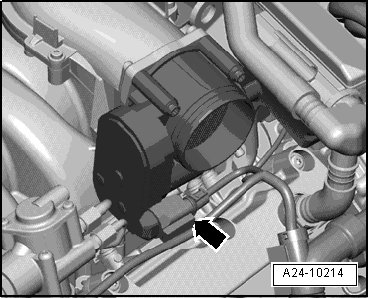
• The Throttle Valve Control Module 2 (J544) is shown. The Throttle Valve Control Module (J338) is similar.
Checking internal resistance
- Using a multimeter, check the Throttle Drive (for Electronic Power Control (EPC)) (G186) at the Throttle Valve Control Module (J338) terminals 3 to 5 for resistance.

Specified value: 1.0 to 5.0 ohms (at 20° C)
If the specified value was not obtained:
- Replace the Throttle Valve Control Module (J338).
If the specified value was obtained:
Checking voltage
- Using a Multimeter, check the Throttle Valve Control Module (J338) electrical harness connector terminals 2 to 6 for voltage.

Specified value: at least 4.5 V
- Switch the ignition off.
If the specified value was obtained:
- Replace the Throttle Valve Control Module (J338).
If the specified value was not obtained:
Checking wiring
If the manufacturers test box is being used. Perform the following step.
- Install the test box.
If the manufacturers test box is not being used. Perform the following step.
- Remove the Motronic Engine Control Module (ECM) (J623). Refer to => [ Engine Control Module, Removing and Installing ] Engine Control Module, Removing and Installing.
- Using a Multimeter, check the Throttle Valve Control Module (J338) electrical harness connector terminals to the Motronic Engine Control Module (ECM) (J623) electrical harness connector T60a terminals for an open circuit.


Specified value: 1.5 ohms max.
If the specification is not obtained:
- Check the wiring for a short circuit to each other, Battery (+), and Ground (GND) or an open circuit.
- Check the electrical harness connector for damage, corrosion, lose or broken terminals.
- If necessary, repair the faulty wiring connection.
If no malfunction is detected in the wiring and if the voltage supply was not OK:
- Replace Motronic Engine Control Module (ECM) (J623). Refer to => [ Engine Control Module, Removing and Installing ] Engine Control Module, Removing and Installing
Assembly is performed in the reverse order of removal.
Final procedures
After repair work, the following work steps must be performed in the following sequence:
1. Check the DTC memory. Refer to => [ Diagnostic Mode 03 - Read DTC Memory ] Diagnostic Mode 03 - Read DTC Memory.
2. If necessary, erase the DTC memory. Refer to => [ Diagnostic Mode 04 - Erase DTC Memory ] Diagnostic Mode 04 - Erase DTC Memory.
3. If the DTC memory was erased, generate readiness code. Refer to => [ Readiness Code ] Monitors, Trips, Drive Cycles and Readiness Codes.
- End of diagnosis.
Throttle Valve Control Module 2
The Throttle Valve Control Module 2 (J544) is controlled by the Engine Control Module (ECM) 2 (J624).
• Use only gold-plated terminals when servicing terminals in harness connector of Throttle Valve Control Module 2 (J544).
Special tools, testers and auxiliary items required
• Multimeter.
• Wiring diagram.
Test requirements
• The Engine Control Module (ECM) 2 (J624) fuses OK.
• Battery voltage at least 12.5 volts.
• All electrical consumers such as, lights and rear window defroster, switched off.
• Vehicles with automatic transmission, shift selector lever into position "P" or "N".
• A/C switched off.
• Ground (GND) connections between engine/transmission/chassis OK.
• Throttle valve must not be damaged or dirty.
• Coolant Temperature at least 80° C.
Function
Throttle valve operation occurs by an electric motor (Throttle Drive (for Electronic Power Control (EPC)) (G186)) in the Throttle Valve Control Module and is operated by the Motronic Engine Control Module (ECM) according to the specifications of Throttle Position (TP) Sensor (G79)/Accelerator Pedal Position Sensor 2 (G185).
The Throttle Valve Control Module (J338) Contains the following components:
• Throttle Drive (for Electronic Power Control (EPC)) (G186)
• Throttle Drive Angle Sensor 1 (for Electronic Power Control (EPC)) (G187)
• Throttle Drive Angle Sensor 2 (for Electronic Power Control (EPC)) (G188)
Function test
- Connect the scan tool.
- Switch ignition on.
- Using the scan tool, check the throttle valve position (absolute) at idle stop:

- Slowly depress the accelerator pedal to Wide Open Throttle (WOT) while observing the percentage display. The percentage display must increase uniformly.
- Using the scan tool, check the throttle valve position (absolute) at Wide Open Throttle (WOT):

- End diagnosis and switch ignition off.
If the specified values are not obtained:
Procedure
- Remove the rear engine cover - 2 -.
- Disconnect the Throttle Valve Control Module 2 (J544) electrical harness connector - arrow -.
Checking internal resistance
- Using a multimeter, check the Throttle Drive (for Electronic Power Control (EPC)) (G186) at the Throttle Valve Control Module 2 (J544) terminals 3 to 5 for resistance.
Specified value: 1.0 to 5.0 ohms (at 20° C)
If the specified value was not obtained:
- Replace the Throttle Valve Control Module 2 (J544).
If the specified value was obtained:
Checking voltage
- Using a Multimeter, check the Throttle Valve Control Module 2 (J544) electrical harness connector terminals 2 to 6 for voltage.
Specified value: at least 4.5 V
- Switch the ignition off.
If the specified value was obtained:
- Replace the Throttle Valve Control Module 2 (J544).
If the specified value was not obtained:
Checking wiring
If the manufacturers test box is being used. Perform the following step.
- Install the test box.
If the manufacturers test box is not being used. Perform the following step.
- Remove the Throttle Valve Control Module 2 (J544). Refer to => [ Engine Control Module, Removing and Installing ] Engine Control Module, Removing and Installing.
- Using a Multimeter, check the Throttle Valve Control Module 2 (J544) electrical harness connector terminals to the Engine Control Module (ECM) 2 (J624) electrical harness connector T60b terminals for an open circuit.

Specified value: 1.5 ohms max.
If the specification is not obtained:
- Check the wiring for a short circuit to each other, Battery (+), and Ground (GND) or an open circuit.
- Check the electrical harness connector for damage, corrosion, lose or broken terminals.
- If necessary, repair the faulty wiring connection.
If no malfunction is detected in the wiring and if the voltage supply was not OK:
- Replace Engine Control Module (ECM) 2 (J624). Refer to => [ Engine Control Module, Removing and Installing ] Engine Control Module, Removing and Installing
Assembly is performed in the reverse order of removal.
Final procedures
After repair work, the following work steps must be performed in the following sequence:
1. Check the DTC memory. Refer to => [ Diagnostic Mode 03 - Read DTC Memory ] Diagnostic Mode 03 - Read DTC Memory.
2. If necessary, erase the DTC memory. Refer to => [ Diagnostic Mode 04 - Erase DTC Memory ] Diagnostic Mode 04 - Erase DTC Memory.
3. If the DTC memory was erased, generate readiness code. Refer to => [ Readiness Code ] Monitors, Trips, Drive Cycles and Readiness Codes.
- End of diagnosis.