Knock Sensor: Testing and Inspection
Knock Sensor, Checking
Knock Sensor 1
The following procedure is used to diagnose Knock Sensor (KS) 1 (G61) which is controlled by Motronic Engine Control Module (ECM) (J623).
Special tools, testers and auxiliary items required
• Multimeter.
• Wiring diagram.
Test requirements
• The mounting bolt of Knock Sensor (KS) 1 (G61) tightened to 20 Nm.
• The Motronic Engine Control Module (ECM) (J623) fuses OK.
• Battery voltage at least 12.5 volts.
• All electrical consumers such as, lights and rear window defroster, switched off.
• Vehicles with automatic transmission, shift selector lever into position "P" or "N".
• A/C switched off.
• Ground (GND) connections between engine/transmission/chassis OK.
• Ignition switched off.
Procedure
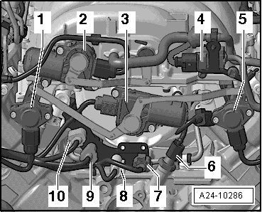
- Remove the front engine cover - 1 -.

- Disconnect the orange Knock Sensor (KS) 1 (G61) electrical harness connector- 9 -.
Checking internal resistance
- Using a Multimeter, check the Knock Sensor (KS) 1 (G61) terminals 1 to 2 for an internal short.

Specified value: infinite (Infinity).
If the specified value was not obtained:
- Replace Knock Sensor (KS) 1 (G61).
If the specified value was obtained:
Checking wiring
If the manufacturers test box is being used. Perform the following step.
- Install the test box.
If the manufacturers test box is not being used. Perform the following step.
- Remove the Motronic Engine Control Module (ECM) (J623). Refer to => [ Engine Control Module, Removing and Installing ] Engine Control Module, Removing and Installing.
- Using a Multimeter, check the Knock Sensor (KS) 1 (G61) electrical harness connector to the Motronic Engine Control Module (ECM) (J623) electrical harness connector T60a for an open circuit.


Specified value: 1.5 ohms Max.
If the specified value was not obtained:
- Check the wiring connection for an open circuit, short circuit to Battery (+) or Ground (GND).
- Check the wiring connection for damage, corrosion, lose or broken terminals.
- If necessary, repair the faulty wiring connection.
If no malfunction is found in the wiring and the resistance was not OK:
- Replace Knock Sensor (KS) 1 (G61).
If no malfunction is found in the wiring and the resistance was OK:
- Replace the Motronic Engine Control Module (ECM) (J623). Refer to => [ Engine Control Module, Removing and Installing ] Engine Control Module, Removing and Installing.
Assembly is performed in the reverse order of removal.
Final procedures
After repair work, the following work steps must be performed in the following sequence:
1. Check the DTC memory. Refer to => [ Diagnostic Mode 03 - Read DTC Memory ] Diagnostic Mode 03 - Read DTC Memory.
2. If necessary, erase the DTC memory. Refer to => [ Diagnostic Mode 04 - Erase DTC Memory ] Diagnostic Mode 04 - Erase DTC Memory.
3. If the DTC memory was erased, generate readiness code. Refer to => [ Readiness Code ] Monitors, Trips, Drive Cycles and Readiness Codes.
- End of diagnosis.
Knock Sensor 2
The following procedure is used to diagnose Knock Sensor (KS) 2 (G66) which is controlled by Motronic Engine Control Module (ECM) (J623).
Special tools, testers and auxiliary items required
• Multimeter.
• Wiring diagram.
Test requirements
• The mounting bolt of Knock Sensor (KS) 2 (G66) tightened to 20 Nm.
• The Motronic Engine Control Module (ECM) (J623) fuses OK.
• Battery voltage at least 12.5 volts.
• All electrical consumers such as, lights and rear window defroster, switched off.
• Vehicles with automatic transmission, shift selector lever into position "P" or "N".
• A/C switched off.
• Ground (GND) connections between engine/transmission/chassis OK.
• Ignition switched off.
Procedure
- Remove the front engine cover - 1 -.
- Disconnect the gray Knock Sensor (KS) 2 (G66) electrical harness connector- 10 -.
Checking internal resistance
- Using a Multimeter, check the Knock Sensor (KS) 2 (G66) terminals 1 to 2 for an internal short.
Specified value: infinite (Infinity).
If the specified value was not obtained:
- Replace Knock Sensor (KS) 2 (G66).
If the specified value was obtained:
Checking wiring
If the manufacturers test box is being used. Perform the following step.
- Install the test box.
If the manufacturers test box is not being used. Perform the following step.
- Remove the Motronic Engine Control Module (ECM) (J623). Refer to => [ Engine Control Module, Removing and Installing ] Engine Control Module, Removing and Installing.
- Using a Multimeter, check the Knock Sensor (KS) 2 (G66) electrical harness connector to the Motronic Engine Control Module (ECM) (J623) electrical harness connector T60a for an open circuit.

Specified value: 1.5 ohms Max.
If the specified value was not obtained:
- Check the wiring connection for an open circuit, short circuit to Battery (+) or Ground (GND).
- Check the wiring connection for damage, corrosion, lose or broken terminals.
- If necessary, repair the faulty wiring connection.
If no malfunction is found in the wiring and the resistance was not OK:
- Replace Knock Sensor (KS) 2 (G66).
If no malfunction is found in the wiring and the resistance was OK:
- Replace the Motronic Engine Control Module (ECM) (J623). Refer to => [ Engine Control Module, Removing and Installing ] Engine Control Module, Removing and Installing.
Assembly is performed in the reverse order of removal.
Final procedures
After repair work, the following work steps must be performed in the following sequence:
1. Check the DTC memory. Refer to => [ Diagnostic Mode 03 - Read DTC Memory ] Diagnostic Mode 03 - Read DTC Memory.
2. If necessary, erase the DTC memory. Refer to => [ Diagnostic Mode 04 - Erase DTC Memory ] Diagnostic Mode 04 - Erase DTC Memory.
3. If the DTC memory was erased, generate readiness code. Refer to => [ Readiness Code ] Monitors, Trips, Drive Cycles and Readiness Codes.
- End of diagnosis.
Knock Sensor 3
The following procedure is used to diagnose Knock Sensor 3 (G198) which is controlled by Engine Control Module (ECM) 2 (J624).
Special tools, testers and auxiliary items required
• Multimeter.
• Wiring diagram.
Test requirements
• The mounting bolt of Knock Sensor 3 (G198) tightened to 20 Nm.
• The Engine Control Module (ECM) 2 (J624) fuses OK.
• Battery voltage at least 12.5 volts.
• All electrical consumers such as, lights and rear window defroster, switched off.
• Vehicles with automatic transmission, shift selector lever into position "P" or "N".
• A/C switched off.
• Ground (GND) connections between engine/transmission/chassis OK.
• Ignition switched off.
Procedure
- Remove the front engine cover - 1 -.
- Disconnect the white Knock Sensor 3 (G198) electrical harness connector- 8 -.
Checking internal resistance
- Using a Multimeter, check the Knock Sensor 3 (G198) terminals 1 to 2 for an internal short.
Specified value: infinite (Infinity).
If the specified value was not obtained:
- Replace Knock Sensor 3 (G198).
If the specified value was obtained:
Checking wiring
If the manufacturers test box is being used. Perform the following step.
- Install the test box.
If the manufacturers test box is not being used. Perform the following step.
- Remove the Engine Control Module (ECM) 2 (J624). Refer to => [ Engine Control Module, Removing and Installing ] Engine Control Module, Removing and Installing.
- Using a Multimeter, check the Knock Sensor 3 (G198) electrical harness connector to the Engine Control Module (ECM) 2 (J624) electrical harness connector T60b for an open circuit.

Specified value: 1.5 ohms Max.
If the specified value was not obtained:
- Check the wiring connection for an open circuit, short circuit to Battery (+) or Ground (GND).
- Check the wiring connection for damage, corrosion, lose or broken terminals.
- If necessary, repair the faulty wiring connection.
If no malfunction is found in the wiring and the resistance was not OK:
- Replace Knock Sensor 3 (G198).
If no malfunction is found in the wiring and the resistance was OK:
- Replace the Engine Control Module (ECM) 2 (J624). Refer to => [ Engine Control Module, Removing and Installing ] Engine Control Module, Removing and Installing.
Assembly is performed in the reverse order of removal.
Final procedures
After repair work, the following work steps must be performed in the following sequence:
1. Check the DTC memory. Refer to => [ Diagnostic Mode 03 - Read DTC Memory ] Diagnostic Mode 03 - Read DTC Memory.
2. If necessary, erase the DTC memory. Refer to => [ Diagnostic Mode 04 - Erase DTC Memory ] Diagnostic Mode 04 - Erase DTC Memory.
3. If the DTC memory was erased, generate readiness code. Refer to => [ Readiness Code ] Monitors, Trips, Drive Cycles and Readiness Codes.
- End of diagnosis.
Knock Sensor 4
The following procedure is used to diagnose Knock Sensor 4 (G199) which is controlled by Engine Control Module (ECM) 2 (J624).
Special tools, testers and auxiliary items required
• Multimeter.
• Wiring diagram.
Test requirements
• The mounting bolt of Knock Sensor 4 (G199) tightened to 20 Nm.
• The Engine Control Module (ECM) 2 (J624) fuses OK.
• Battery voltage at least 12.5 volts.
• All electrical consumers such as, lights and rear window defroster, switched off.
• Vehicles with automatic transmission, shift selector lever into position "P" or "N".
• A/C switched off.
• Ground (GND) connections between engine/transmission/chassis OK.
• Ignition switched off.
Procedure
- Remove the front engine cover - 1 -.
- Disconnect the blue Knock Sensor 4 (G199) electrical harness connector- 7 -.
Checking internal resistance
- Using a Multimeter, check the Knock Sensor 4 (G199) terminals 1 to 2 for an internal short.
Specified value: infinite (Infinity).
If the specified value was not obtained:
- Replace Knock Sensor 4 (G199).
If the specified value was obtained:
Checking wiring
If the manufacturers test box is being used. Perform the following step.
- Install the test box.
If the manufacturers test box is not being used. Perform the following step.
- Remove the Engine Control Module (ECM) 2 (J624). Refer to => [ Engine Control Module, Removing and Installing ] Engine Control Module, Removing and Installing.
- Using a Multimeter, check the Knock Sensor 4 (G199) electrical harness connector to the Engine Control Module (ECM) 2 (J624) electrical harness connector T60b for an open circuit.

Specified value: 1.5 ohms Max.
If the specified value was not obtained:
- Check the wiring connection for an open circuit, short circuit to Battery (+) or Ground (GND).
- Check the wiring connection for damage, corrosion, lose or broken terminals.
- If necessary, repair the faulty wiring connection.
If no malfunction is found in the wiring and the resistance was not OK:
- Replace Knock Sensor 4 (G199).
If no malfunction is found in the wiring and the resistance was OK:
- Replace the Engine Control Module (ECM) 2 (J624). Refer to => [ Engine Control Module, Removing and Installing ] Engine Control Module, Removing and Installing.
Assembly is performed in the reverse order of removal.
Final procedures
After repair work, the following work steps must be performed in the following sequence:
1. Check the DTC memory. Refer to => [ Diagnostic Mode 03 - Read DTC Memory ] Diagnostic Mode 03 - Read DTC Memory.
2. If necessary, erase the DTC memory. Refer to => [ Diagnostic Mode 04 - Erase DTC Memory ] Diagnostic Mode 04 - Erase DTC Memory.
3. If the DTC memory was erased, generate readiness code. Refer to => [ Readiness Code ] Monitors, Trips, Drive Cycles and Readiness Codes.
- End of diagnosis.