Fuel Level Sensor 2
Fuel Level Sensor 2
Special tools, testers and auxiliary items required
• Union nut tool (T40068 A)
Removing
Observe safety precautions. Refer to => [ Safety Precautions ] Fuel Supply System.
Observe rules for cleanliness. Refer to => [ Clean Working Conditions ] [1][2]Fuel Injection System.
CAUTION!
Danger due to escaping fuel.
• To prevent large quantities of fuel from escaping when removing fuel level sensor 2 , fuel tank may only be a maximum of 1/4 full. Drain fuel tank if necessary. Refer to => [ Fuel Tank, Draining ] Procedures.
CAUTION!
Risk of destroying electrical components when battery is disconnected.
• Follow the instructions when disconnecting the battery.
- Switch off ignition.
Sedan:
- Fold the luggage compartment floor upward.
Wagon:
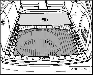
- Remove luggage compartment cargo floor - 1 - and spare wheel cover - 2 -.
All:

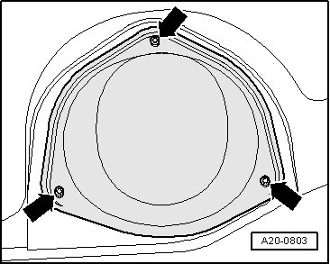
- Release the retaining clips - arrows - with a screwdriver - 2 - and remove the cover - 1 -.
- Disconnect ground (GND) strap at battery ground (GND) terminal - arrow -.

- Remove rear seat bench.
- Unbolt cover for left locking flange - arrows -.

CAUTION!
Danger due to escaping fuel.
• To prevent large quantities of fuel from escaping when removing fuel level sensor 2, fuel tank may only be a maximum of 1/4 full.
- Remove the left union nut with the (T40068 A) - arrow -.
• The plastic catch on the threaded ring breaks off when the union nut is loosened.
- Carefully pull the fuel level sensor 2 - 1 - and suction jet pump - 2 - partially out of the fuel tank opening.

• When removing, be sure not to bend floater arm of fuel level sensor 2.
- Unclip the suction jet pump from the locking flange.

- Separate the electrical connector - 1 -.
- Release retaining tabs - arrows - with a screwdriver and remove the fuel level sensor 2.
Installing
• Assembly overview, refer to => [ Fuel Delivery Unit and Fuel Level Sensor Assembly Overview ] Fuel Delivery Unit and Fuel Level Sensor Assembly Overview.
• Tightening specifications, refer to => [ Fastener Tightening Specifications ] Fuel Supply System - Fastener Tightening Specifications.
Installation is performed in the reverse order of removal, noting the following:
• Always replace seal and union nut.
- Insert fuel level sensor 2 in guides on locking flange and press in until it engages.
- Connect the electrical connection and check that it is securely engaged.
- Clip the suction jet pump - 3 - to the locking flange - 2 - so that it is audibly engaged.

- Check whether fuel delivery line is connected to suction jet pipe with at least 3 cable ties.
• When inserting, be sure not to bend floater arm on fuel level sensor 2.
- Carefully insert fuel level sensor 2 in fuel tank opening.
- Slide the new gasket - 1 - over the sealing flange and insert it in the groove on the fuel tank.
- Slide the union nut - 1 - over the left arm and press the sealing flange forcefully - 2 - into the installation position with the left hand - arrow -.

• The tab - 4 - on locking flange must lie between tabs - 3 - and - 5 - on threaded ring.
- With the right hand, slide the union nut - 1 - off the left arm while continuing the press the sealing flange - 2 - down forcefully with the left hand - arrow -.

- Position the union nut - 1 - with the right hand so the double ridge - 5 - on the ribbing lies over the tab - 3 - on the sealing flange (approximately the 10 o'clock position). This makes sure the union nut engages at the beginning of the threads immediately when tightening it - 4 -.
- Continue pressing the sealing flange down forcefully.

- Rotate the sealing ring approximately 390° with the right hand until the double ridge - 1 - is in the 12 o'clock position while continuing to press the sealing flange down forcefully with the left hand.

CAUTION!
There is a risk of the locking flange threaded connection leaking.
• Press the locking flange down firmly when tightening the union nut so it does not rotate too.
- Tighten the left sealing flange union nut with the (T40068 A).
• Verification: The double ridge - 1 - must now be between the 5 o'clock and 6 o'clock positions.

- Install rear seat bench.
- Connect battery. Observe safety precautions after connecting battery.
- After installing the fuel level sensor 2, fill the vehicle with at least 5 liters of fuel.