Manual Transmission 0B2 and 0B4
Engine, Installing
Special tools, testers and auxiliary items required
• Socket AF 16 mm (V.A.G 1332/14)
• Assembly Aid (T40169)
• Transportation Lock (T40170)
Tightening Specifications
• Tightening specifications only apply to lightly greased, oiled, phosphated or blackened nuts and bolts.
• Additional lubricants, such as engine or transmission oil are permissible, although lubricants containing graphite are not.
• Do not use any parts that have had the lubrication removed.
• Tolerance for tightening specifications ±15%.

Subframe mount. Refer to => [ Subframe Mount Assembly Overview ] Subframe Mount Assembly Overview.
Ground bolt to strut tower - tightening specification

- Tighten the ground bolt - 1 - to 9 Nm.
Tightening specification for Ground (GND) cable to the longitudinal member
- Tighten nut - arrow - to 9 Nm.
Engine to manual transmission


• Audi A4 from VIN 8K-9-066500, Audi A5 from VIN 8T-9-008000: The aluminum bolts - 2 through 11 - may be used two times. After using the bolts once, mark them with an "X" made by a chisel - arrow -.

• To avoid damaging the bolts when marking them, do not clamp them in a vise. Insert the bolt in a 14 mm socket with a 1/2 inch drive ratchet which is clamped into a vise, as shown in the illustration.
• Do not used bolts marked with an "X" again.
Procedure
• Replace bolts which have been tightened to torque.
• Replace self-locking nuts and bolts as well as sealing rings, seals and O-rings.
• In vehicles with manual transmissions, there is a needle bearing in the drive plate. Check if the needle bearing is inserted before installing. Refer to => [ Needle Bearing on Drive Plate ] Service and Repair.
• Secure all hose connections with hose clamps appropriate for the model.
• In order to be able to securely mount the air guide hoses on their connectors, spray the bolts on the previously used clamps with a rust remover.
• During installation, all cable ties must be re-installed at the same location.
- Install engine supports and engine mount. Refer to => [ Subframe Mount Assembly Overview ] Subframe Mount Assembly Overview.
- Clean the threaded holes in the cylinder block for connecting the engine and transmission using a thread tap before installing the transmission.
- Complete the following steps before connecting the engine and transmission:
- Insert the Assembly Aid (T40169) into the transmission housing and clutch module from underneath as illustrated.

• The assembly aid must engage in the semi-circular opening - 1 - and in the inspection hole - 2 -.
• The inspection hole is only in one location on the circumference so rotate the clutch module as needed.
- Install the assembly aid bolt into the hole on the transmission housing.
- Install the Transport Lock (T40170) into the transmission housing from underneath and secure it to the flange shaft - 1 -.

- Make sure the alignment sleeves - A - for centering the engine and transmission in the cylinder block are present. Insert the alignment sleeves if they are missing.
- Determine if the engine/transmission aluminum bolts can be used again and mark them if necessary.
- Position the transmission on the engine and tighten the bolts - 1 through 11 -.
- Remove the Transport Lock (T40170) and Assembly Aid (T40169).
• The following procedure is necessary to assure that the clutch module contacts the drive plate evenly and does not get bent.
- Insert Adapter (T40058) guide pins as follows:

• The large diameter - arrow 1 - faces the engine.
• Small diameter - arrow 2 - points to adapter.
- Rotate the crankshaft one complete rotation (360°) in engine rotation direction - arrow - with the Adapter (T40058).

• The inspection hole - arrow - must be visible through the opening in the transmission housing.

- Secure the clutch module to the drive plate as follows:
• Tighten the bolt with the Ring Spanner Insert AF 16 (V.A.G 1332/14).
- Install the first bolt - arrow - by hand (2 Nm).

- Rotate the crankshaft with the Socket (T40058) 180° in direction of engine rotation - arrow -.
- Tighten the bolts that are accessible in this position to the tightening specification.
- Turn the crankshaft 60° further and tighten the remaining 5 bolts to the tightening specification.
- Install the power steering hydraulic oil lines.
- Install the catalytic converters. Refer to: Left => [ Left Catalytic Converter, Manual Transmission ] Left Catalytic Converter, Manual Transmission, right => [ Right Catalytic Converter, Manual or Multitronic Transmission ] Right Catalytic Converter, Manual or Multitronic Transmission.
- Install the left and right drive axles on the transmission flange shafts.
- Next, raise engine/transmission assembly high enough using Scissor Lift Table (VAS 6131 A) until dimension - a - is reached between subframe and body.

• Dimension - a - = at least 100 mm.
- Install shift rod and pivot rod.
- Continue raising the engine/transmission assembly using the Scissor Lift Table (VAS 6131 A).
- Align the subframe and transmission carrier using the marks made on the longitudinal members during removal.
- Tighten the subframe bolts only to the tightening specifications, do not tighten them further (tighten the bolts only after axle alignment).

Risk of accident due to loose connections.
• If the bolts in the subframe are not tightened to final torque, vehicle must not be driven.
- Tighten the tunnel crossmember bolts - arrow -.

The rest is in reverse order of removal, note the following:
- Install clutch slave cylinder.
- Install universal joint on the steering gear.
- Install driveshaft.
- Install front muffler. Refer to => [ Front Muffler ] Front Muffler.
- Install exhaust system free of stress. Refer to => [ Exhaust System, Installing ] Service and Repair.
- Install front crossmember.
- Install subframe crossbrace, upper control arm and stabilizer bar and tighten the suspension strut on the control arm.
- Install brake caliper.
- Install Engine Control Module (ECM).
- Electrical connections and routing.
- Install wires, Terminal 30 Wire Junction 2 (TV22) and the engine compartment E-box cover.
- Install tower brace.
- Install washer fluid reservoir filler tube.
- Install refrigerant lines.
- Follow measures after connecting battery.
Risk of destroying control modules with excess voltage.
• Do not use a battery charger for starting assistance!
- Install air filter housing.
- Install lock carrier braces.
- Fill the engine oil and check the oil level.
- Before starting engine for the first time, check the fluid level in power steering reservoir.
• Power-steering pump must not run dry.
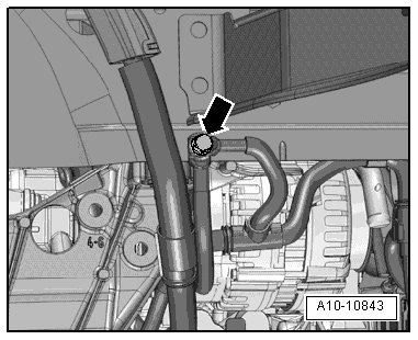
- Connect coolant hose with the connector coupling => [ Connect the coolant hose with the connector
coupling ] Radiator and Coolant Fan Assembly Overview

- Fill with coolant. Refer to => [ Filling ] Procedures.
• Do not use drained coolant in the following situations:
• If the cylinder head or cylinder block was replaced.
• If the coolant is contaminated.
- Fill refrigerant circuit.
- Install wheel housing liners.
- Install front wheels and perform an alignment.
Risk of accident due to loose connections.
• Tighten the subframe bolts to the specification after performing axle alignment.
- Install noise insulation.