Cylinder Head, With Screwdriver Access
Cylinder Head, with Screwdriver Access
• Camshafts with screwdriver access have notches in the camshafts, refer to => [ Screwdriver Access ] Cylinder Head, Screwdriver Access.
Special tools, testers and auxiliary items required
• Assembly Tool (T10352)
• Counter Hold Tool (T10355)
• Locking Pin (T40011)
• Lever (T40243)
• Locking Tool (T40267)
• Camshaft Clamp (T40271)
• Ignition Coil Puller (T40039)
• Engine Bung Set (VAS 6122)
• Polydrive Bit and Drive Socket (T10070)
• Drift (T40196)
• Spark Plug Removal Tool (3122 B)
Removing
• During installation, cable ties must be installed at the same location.
• Always seal off any open channels in the intake and exhaust tract with plugs. For example, use the plugs from the (VAS 6122).
- Remove the front noise insulation.
Risk of scalding due to hot steam and hot coolant.
• The coolant system is under pressure when the engine is warm.
• Reduce pressure by covering coolant reservoir cap with a cloth and carefully opening.
- Drain the coolant. Refer to => [ Coolant, Draining and Filling ] Service and Repair.
- Remove the front exhaust pipe/front muffler. Refer to => [ Front Exhaust Pipe and Front Muffler ] Front Exhaust Pipe and Front Muffler.
- Remove the engine cover - arrows -.

- Remove the plenum chamber covers - 1, 2 and 3 -.

- Disconnect the vacuum connection - 2 - from the plenum chamber bulkhead by remove the vacuum hose - 3 - on the back side - arrow -.

- Remove the coolant hoses on the back of the cylinder head.

Risk of contamination to the fuel system.
• Note rules of cleanliness for working on the fuel injection system. Refer to => [ Clean Working Conditions ] Clean Working Conditions.
- Disconnect fuel lines - 1 and 2 -.
- Remove the front bumper cover and the bumper.
- Install the lock carrier in service position. Procedures
- Disconnect the connector - 1 - from the Mass Airflow (MAF) sensor (G70).

- Loosen the air intake hose - 2 -.
- Remove the air filter housing upward - arrows -.
- Loosen the hose clamps - arrows - and remove the air guide hose.

- Disconnect the following connectors.

2 Disconnect from Knock Sensor (KS) 1 (G61)
3 From the Intake Manifold Runner Control (IMRC) Valve (N316) , Fuel Pressure Sensor (G247) and the Camshaft Position (CMP) sensor (G40).
4 From the fuel injectors
5 From the throttle valve control module (J338).
6 From the Intake Air Temperature (IAT) sensor (G42).
- Disconnect the connector - 2 - and free up the wire.

- Remove the coolant line bracket - arrow -.

• The engine is not shown in the illustrations that follow.
- Remove the intake manifold bracket by removing the mounting nut - 1 - and bolt - 2 -.

- Disconnect the coolant hose - arrow -.

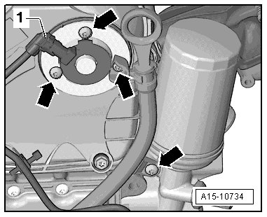
- Remove the bolts - 1 and 2 - and move the oil supply line to the side.

- Remove the bolt - 3 - and move the coolant line to the side.
- Loosen the hose clamp - arrow -, pull off the air guide hose and move it to the side.

- Disconnect the connectors - 1 and 4 - from the oil pressure switch (F22) and the reduced oil pressure switch (F378).

- Disconnect the connectors - 1 and 2 - and free up the wire.

- Remove the bolts - arrows - and then remove the turbocharger support.

- Remove the bolts - arrows - on the oil return line.

- Remove the nuts - arrows - and push the catalytic converter to the rear.

- Disconnect the connector from the camshaft adjustment valve 1 (N205) - 1 -.
- Remove the bolts - arrows - and then the camshaft adjustment valve 1.
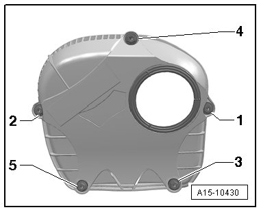
- Remove the bolts - 1 through 5 - and the upper timing chain guard.
- Remove the bolts on the ignition coil connector strip.
- Release the connector - arrows - and disconnect all the connectors at the same time from the ignition coils.

- Remove the ignition coils with the (T40039).

- Remove the spark plugs using a (3122 B).
- Disconnect the hose for the crankcase ventilation - 1 -.

- Remove the bolts - arrows - and then remove the crankcase ventilation from the hose - 2 - in direction of - arrow -.
- Disconnect the connectors - arrows - from the camshaft adjuster actuators.

- Remove the camshaft adjuster actuators - arrows -.

- Turn the sealing plug - arrows - counterclockwise 90° in the direction of the - arrow - and remove it.

- Remove the ball head - 1 through 2 -.
- Remove the cap.
- Rotate the vibration damper using the Counter Hold Tool (T10355) into the Top Dead Center (TDC) position.

• The notch on the vibration damper and the marking on the lower timing chain guard must be opposite one another - arrow -.
• The markings - 1 - on the camshafts must point upward.
- Remove the cylinder head bolts - 1 and 2 - with the (T10070).


Danger of causing damage to the engine.
• The (T40196) may be installed only in the shown positions.
- Install the (T40196) as illustrated.
- Turn the crankshaft 4 complete turns in the direction of engine rotation.
- Remove the (T40196).

The control valve has a left thread.
- Remove the control valve using the (T10352) or (T10352/1) in direction of - arrow - depending on the version.
- Remove the bolts - arrows - and remove the bearing bracket.

- Rotate the vibration damper using the (T10355) into the TDC position.
• The notch on the vibration damper and the marking on the lower timing chain guard must be opposite one another - arrow -.
• The markings - 1 - on the camshafts must point upward.
- Mark the camshaft timing chain and the cylinder head - arrows - to match the marking on the chain sprockets - 1 - with a waterproof marker.

- In addition, mark the camshaft timing chain to the camshaft timing chain guide rail - 2 - with a permanent marker.
- Remove the plug - arrow -.

- Remove the bolts - arrows -.

- Remove the bolt - arrow -.

Two Different Chain Tensioners may be Installed Depending on the Version:

Version 1
- Install the (T40243) - arrows -.
- Insert a scriber or a suitable screwdriver into the opening for the chain tensioner in the direction of the - arrow 1 - to lift up the locking wedge for the chain tensioner, slowly press down the (T40243) and hold it in the direction of the - arrow 2 -.
- Secure the chain tensioner using (T40011).

Version 2

- Install the (T40243) - arrows -.
- Press the chain tensioner locking ring - 1 - together and slowly press and hold the (T40243) in the direction of the - arrow -.
- Secure the chain tensioner with the (T40267).

All Versions

- Remove the (T40243).
- Bolt the (T40271/2) to the cylinder head and push the chain sprocket splines in the direction of the - arrow 2 -. If necessary, turn the intake camshaft with a wrench in the direction of the - arrow 1 -.
- Remove the bolt - 1 - and guide the tensioning rail - 2 - downward.

- Attach the (T40271/1) to the cylinder head.

- Turn the exhaust camshaft with the wrench in the direction of the - arrow 1 - and slide the (T40271/1) in the chain sprocket splines in the direction of the - arrow 2 -.
- Remove the upper guide track - 1 - by unlocking the latch with a screwdriver and pushing the guide track forward.

- Remove camshaft timing chain from chain sprockets.
Risk of damaging valves and piston crowns.
• If the camshaft timing chain was removed from the cylinder head, then the crankshaft may not be turn further.
- Remove the bolts - arrows -.

- Remove the cylinder head bolts with the (T10070) in the following sequence: - 1 through 8 -.
• Make sure all wires and cables are disconnected.
• Pay attention to the tension and guide tracks when lifting the cylinder head.
- Remove the cylinder head.
- Lay the cylinder head on a soft surface, such as foam.
Installing
• Tightening specifications, refer to => [ Cylinder Head Overview, with Screwdriver Access ] Cylinder Head Overview, With Screwdriver Access.
The sealing surfaces could be damaged.
• Carefully remove sealant residue from cylinder head and cylinder block.
• Make sure that no long scrapes or scratches result.
Risk of damaging cylinder block.
• There must be no oil or coolant in the blind holes for the cylinder head bolts in the cylinder block.
Risk of cylinder head seal leaking.
• Carefully remove all grinding and sanding residue.
• Only unpack new cylinder head gasket immediately prior to installation.
• To prevent cylinder head seal silicone layer and recessed area from being damaged, always handle seal extremely carefully.
Risk of damaging open valves.
• If a replacement cylinder is installed, only remove plastic base right before cylinder head is installed to protect open valves.
Risk of damaging valves and piston heads after working on valve train.
• To ensure valves do not strike pistons when starting, carefully rotate engine at least 2 full revolutions.
• Replace the bolts which are being tightened with an additional turn.
• Replace self-locking nuts, sealing rings, seals and O-rings.
• If a replacement cylinder is installed, the contact surfaces between the hydraulic adjusting elements, roller rocker levers and cam running surfaces must be lubricated before installing the camshafts.
• The hose supports, air guide pipes and hoses must be free of oil and grease before installing.
• Secure all hose connections with hose clamps of the same type as those equipped by the factory. Refer to the Parts Catalog.
• To mount the charge hoses on their connectors securely, spray the bolts on the used clamps with rust remover before installing.
• It is necessary to replace all the coolant and engine oil whenever the cylinder head or the cylinder head gasket are replaced.
When using a New Cylinder Head
- Mark the camshaft sprocket to the (T40271/1) and the (T40271/2) - arrow -.
- Turn the intake camshaft with a wrench in the direction of the - arrow 1 -, slide the (T40271/2) out of the chain sprocket splines in the direction of the - arrow 2 - and bring the camshaft into the rest position.

- Remove the (T40271/2).
- Turn the exhaust camshaft with a wrench in the direction of the - arrow 1 -, slide the (T40271/1) out of the chain sprocket splines in the direction of the - arrow 2 - and bring the camshaft into the rest position.

- Remove the (T40271/1).
- Transfer the self-made markings from the old camshafts to the new camshafts.
- Attach the (T40271/2) to the cylinder head.

- Turn the intake camshaft in the direction of the - arrow 1 - until the markings - 3 - align with the (T40271/2).
- Slide the (T40271/2) into the chain sprocket splines in the direction of the - arrow 2 -.
- Attach the (T40271/1) to the cylinder head.

- Turn the exhaust camshaft in the direction of the - arrow 1 - until the marking - 3 - aligns with the (T40271/1).
- Slide the (T40271/1) into the chain sprocket splines in the direction of the - arrow 2 -.
All

- Set cylinder head gasket in place.
• Pay attention to centering pins in cylinder block - arrows -.
• Observe cylinder head seal location, identification: The part number must be visible from the intake side.
When rotating the crankshaft, make sure the timing chain cannot damage any other components.
- In the event the crankshaft has been rotated in the meantime: Set piston of cylinder 1 to Top Dead Center (TDC) and turn crankshaft back again slightly.
- Position the cylinder head.
- Install the bolts - 1 through 8 -.

- Install the cylinder head bolts in the following sequence - 1 through 8 - with the (T10070) and tighten them all together in 3 stages - item 6 - => [ (Item 6) Cylinder Head Bolt ] Cylinder Head Overview, With Screwdriver Access.
- Tighten the bolts - arrows - in two steps - item 4 - => [ (Item 4) Bolt ] Cylinder Head Overview, With Screwdriver Access.
• There is no requirement to tighten the cylinder head bolts after repairs.
- Rotate the vibration damper using the (T10355) into the TDC position - arrow -.

• The notch on the vibration damper must line up with the arrow marking on the timing chain lower cover.
- Position the markings on the chain links - arrows - at the chain sprockets - 1 - to install the camshaft timing chain.

- Install the upper glide track - 2 -.
- Turn the exhaust camshaft in the direction of the - arrow 1 -, slide out the (T40271/1) from the chain sprocket splines in the direction of the - arrow 2 - and release the camshaft.

- Remove the (T40271/1).
- Move the tensioning rail - 2 - up and install the bolt - 1 -.
- Turn the intake camshaft in the direction of the - arrow 1 -, slide out the (T40271/2) from the chain sprocket splines in the direction of the - arrow 2 - and release the camshaft.

- Remove the (T40271/2).
- Check the valve timing. The camshaft timing chain and cylinder head - arrows - must align with the markings on the chain sprocket - 1 -.

- The markings for the camshaft timing chain and the camshaft timing chain glide track - 2 - must be opposite one another.
- The notch on the vibration damper must be opposite the marking on the lower timing chain guard - 3 -.
- Mount the bearing bracket and the bolts - arrows - hand-tight.
- Remove the (T40011) or the (T40267) , depending on the version.
- Tighten the bolts - arrows -. Refer to => [ Camshaft Timing Chain Overview ] Camshaft Timing Chain Overview.
- Install the bolt - arrow -.
- Install the control valve - item 6 - => [ (Item 6) Control Valve ] Camshaft Timing Chain Overview.
- Install the (T40196) as illustrated.

- Turn the crankshaft 4 complete turns in the direction of engine rotation.
- Remove the (T40196).
- Install the bolts - 1 and 2 -.
- Install the cylinder head bolts in the following sequence - 1 and 2 - with the (T10070) and tighten them all together in 3 stages - item 6 - => [ (Item 6) Cylinder Head Bolt ] Cylinder Head Overview, With Screwdriver Access.
Further assembly is performed in the reverse order of removal, thereby observing the following:
- Change the engine oil.
- Install the upper timing chain guard. Refer to => [ Upper Timing Chain Cover ] Upper Timing Chain Cover.
- Replace coolant. Refer to => [ Coolant, Draining and Filling ] Service and Repair.
- Install the catalytic converter. Refer to => [ Catalytic Converter ] Catalytic Converter.
- Install the front exhaust pipe/front muffler. Refer to => [ Front Exhaust Pipe and Front Muffler ] Front Exhaust Pipe and Front Muffler.
Do not use a charger as a starting aid. There is the risk that the vehicle control modules could be damaged.