Engine, Installing
Engine, Installing
Special tools, testers and auxiliary items required
• Depth Gauge (VAS 6082)
• Scissor-Type Assembly Platform (VAS 6131 A)
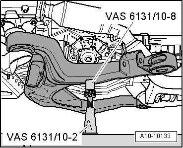
• Support Elements (VAS 6131/10-8)
Tightening Specifications
• Tightening specifications only apply to lightly greased, oiled, phosphate or blackened nuts and bolts.
• Additional lubricants, such as engine or transmission oil are permissible, although lubricants containing graphite are not.
• Do not use any parts that have had the lubrication removed.
• Tolerance for tightening specifications +/- 15%.

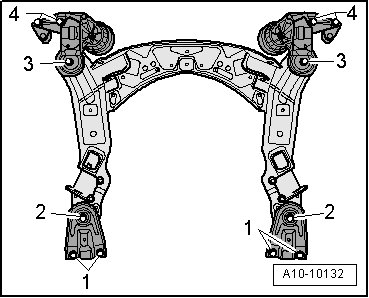
Subframe mount, refer to => [ Subframe Mount Overview ] Subframe Mount Overview.
Automatic Transmission to Engine Fastener


Installing
• Replace bolts which have been tightened to an additional torque.
• Replace self-locking nuts and bolts as well as sealing rings, seals and O-rings.
• To secure torque converter to the drive plate, use new original bolts.
• Always clean threaded bores in transmission flanged shaft for driveshaft of locking fluid residue using a tap before installation.
• The hose connections as well as the air guide pipes and hoses must be free of oil and grease before installing.
• Secure all hose connections with hose clamps appropriate for the model.
• In order to be able to securely mount the air guide hoses on their connectors, spray the screws on the previously used clamps with a rust remover.
• During installation, all cable ties must be installed at the same location.
- Install the left and right engine supports.
- Check whether fitting sleeves for centering engine and transmission in cylinder block are present, insert missing fitting sleeves.
Installation dimension for torque converter, checking.
Risk of destroying ATF pump coupling plate by inserting torque converter incorrectly.
• Check torque converter installation dimension.
• When torque converter is installed correctly, distance - a - between contact surface of threaded holes at torque converter and contact surface of bell housing on automatic transmission is at least 19 mm.

- Before connecting engine and transmission, rotate torque converter and engine drive plate so that one hole or one threaded hole stands at height of opening of the removed starter - arrow -.

- Install intermediate plate between engine and transmission onto alignment bushings.
Risk of destroying transmission due to torque converter inserted incorrectly.
• Keep checking whether the torque converter behind the drive plate can be turned before and during tightening of the bolts at engine/transmission connection.
• If torque converter cannot be rotated, the ATF pump coupling plate and therefore the transmission are destroyed when connections are tightened to final torque.
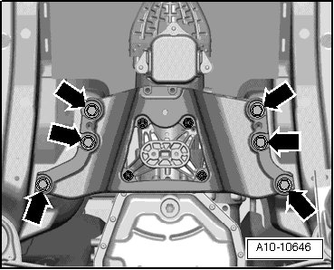
- Position the transmission on the engine and tighten the bolts - 3 through 10 -.
The rest of the installation is performed in reverse order of removal, noting the following.
- Install the starter.
- Secure the ATF pipes.
- Install the front exhaust pipes. Refer to => [ Left Front Exhaust Pipe with Catalytic Converter ] Left Front Exhaust Pipe with Catalytic Converter, => [ Right Exhaust Pipe with Catalytic Converter ] Right Exhaust Pipe with Catalytic Converter.
- Turn spindle of the left support element on engine downward.

- Remove the left support element base plate from the (VAS 6131 A).
- Turn the spindle of the right support element on the engine downward.

- Remove the right support element base plate from the (VAS 6131 A).
- Rotate the front attachment element spindles on the transmission down.

- Remove the support element base plates from the (VAS 6131 A).
• Support points for front of engine, transmission and tunnel cross member remain unchanged.
- Equip the (VAS 6131 A) with the (VAS 6131/10) and (VAS 6131/11) as follows:


• A second technician is required to position subframe onto support elements.
- Mount the subframe on both (VAS 6131/10-8).
- Rotate the support element spindles on both sides up.
- Attach mounting element base plates to the (VAS 6131 A) and tighten to 20 Nm.
- Slowly guide the engine/transmission subassembly and the subframe using the (VAS 6131 A) from underneath into the body.
- Align the subframe and engine mount brackets using the marks made on the longitudinal members during removal.
- Tighten the subframe bolts and engine mount brackets only to the tightening specifications, do not tighten them further (tighten the bolts only after axle alignment).
Risk of accident due to loose connections.
• If the bolts in the subframe are not tightened to final torque, vehicle must not be driven.
- Tighten the tunnel crossmember bolts.
The rest of the installation is performed in reverse order of removal, noting the following:
- Install the selector lever cable and check adjustment.
- Install the drive axles, guide control arms, control arms, stabilizer bar, coupling rods and suspension struts.
- Install the front transverse beam.
- Install the driveshaft.
- Install exhaust system free of stress. Refer to => [ Exhaust System, Installing ] Service and Repair.
- Install A/C compressor.
- Install the power steering pump hydraulic pipe.
- Install the fuel supply hose.
- Install the ribbed belt. Refer to => [ Ribbed Belt ] Ribbed Belt.
- Install the torque support. Refer to => [ Torque Support ] Torque Support.
- Electrical connections and routing.
- Follow the instructions for connecting the battery. Refer to.
Risk of destroying control modules with excess voltage.
• Do not use a battery charger for starting assistance!
- Install and adjust the windshield wiper arms.
- Install the tower brace.
- Check oil level.
- Before starting engine for the first time, check the fluid level in power steering reservoir.
• The power steering pump must not run dry.
- Fuel system, bleeding.
- Fill with coolant => [ Filling ] Procedures.
• Do not use drained coolant in the following situations:
• If the cylinder head or cylinder block was replaced.
• If the coolant is contaminated.
- Check ATF level.
- Align the subframe and both engine mount brackets.
- Install the front wheels.
- Perform an axle alignment.
Risk of accident due to loose connections.
• Tighten subframe bolts to final torque after axle alignment.
- Install the noise insulation.